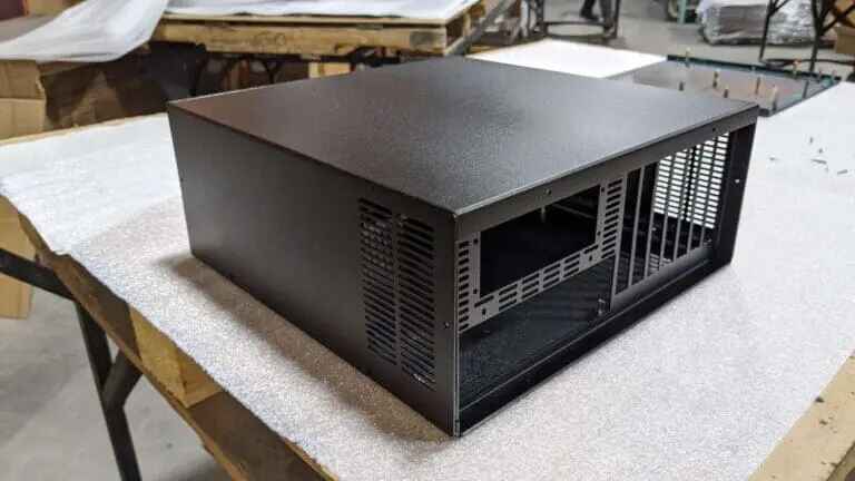
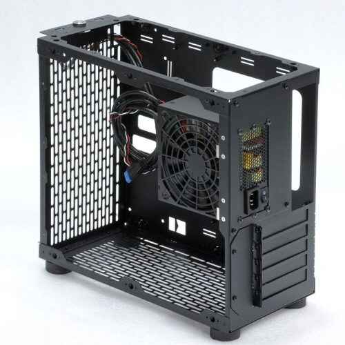
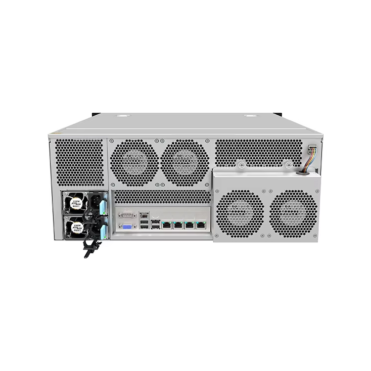
A custom enclosure project should start with the hardware, environment, assembly method, service requirements, and production volume—not with a sheet-metal drawing.
DFM needs to happen before the first prototype. Bend radii, tooling, flange lengths, hole locations, welding access, tolerances, and finishing all affect whether the CAD model can be built consistently.
The first prototype should prove fit, function, assembly, airflow, strength, and service access. It is not simply a prettier version of the drawing.
Tighter tolerances are not automatically better. Control the dimensions that affect interfaces and function; give the manufacturing process room everywhere else.
The real handoff to production happens only after drawings, BOMs, finishes, inspection points, revision levels, and an approved physical sample are aligned.
A good custom metal enclosure manufacturing process removes uncertainty early. A bad one discovers it after metal has already been cut.
A custom metal enclosure looks simple from the outside.
Six panels. A few bends. Some holes. Powder coating. Done.
Except it rarely works that way.
The enclosure may need to hold a motherboard, power supply, fans, drives, GPUs, switches, connectors, filters, rails, cables, brackets, displays, handles, or customer-specific hardware. Each component creates another interface. Each interface creates another opportunity for a dimension, bend, tolerance, tool, finish, or assembly assumption to go wrong.
That is why custom metal enclosure manufacturing is really a product-development exercise disguised as sheet-metal work.
The commercial pressure is also getting harder to ignore. Protolabs’ 2024 product development study (opens in a new tab) surveyed 767 engineers and designers and reported an average product-development journey of about 22 months. At the same time, 82% of respondents said they were constantly looking for ways to accelerate development, while 65% said they needed to develop products faster to stay ahead of competitors.
Speed matters.
But skipping engineering steps is usually the slow way.
What Does the Custom Metal Enclosure Development Process Actually Include?
A practical development sequence normally looks like this:
المرحلة
المخرجات الرئيسية
What Can Go Wrong
1. Requirement definition
Hardware and performance specification
Missing components or conflicting requirements
2. Mechanical architecture
Initial enclosure layout
Poor access, clearance, airflow, or structural support
The important point is that these stages feed one another.
Design affects manufacturing. Manufacturing affects tolerance. Tolerance affects assembly. Assembly affects serviceability. Finishing can even change whether a threaded hole, mating surface, grounding point, or sliding component still works.
Treating each stage as a separate purchasing activity is where projects start leaking time.
Stage 1: Define the Enclosure Around the Real System
The first drawing should not come first.
The requirements should.
For an industrial computer, server, network appliance, control box, storage system, or other electronic enclosure, the engineering team needs to understand what will actually live inside the metal.
A motherboard specification saying “ATX,” for example, does not tell the entire mechanical story. A supplier still needs actual dimensions, standoff locations, I/O placement, adjacent connector space, cable exits, heatsink height, expansion-card geometry, and nearby obstructions.
Labels help.
Drawings decide.
Stage 2: Build the Mechanical Architecture Before Styling the Box
Once the inputs are stable enough, the enclosure architecture can start.
This is where engineers establish:
panel construction
internal brackets
removable covers
mounting tabs
drive cages
stiffeners
جدران المروحة
PSU support
PCIe retention
cable paths
access panels
assembly direction
fastening strategy
One recurring mistake is designing every component individually and checking the complete assembly only near the end.
That is backwards.
The enclosure needs to be reviewed as an assembled system from the beginning.
A technically correct motherboard tray can still fail because a connector sits too close to the wall. A fan can fit perfectly yet become impossible to replace after the PSU is installed. A screw may be visible in CAD but unreachable with a screwdriver on the assembly line.
For computer and server projects, good Sheet Metal Enclosure Design means checking interfaces rather than trusting component-category names alone.
Ask one simple question repeatedly:
Can someone actually build and service this thing?
That catches a lot.
Stage 3: Select Material Based on the Job, Not Habit
Steel and aluminum can both make excellent enclosures.
That does not make them interchangeable.
Cold-rolled steel may offer attractive strength, stiffness, cost, and fabrication characteristics for many indoor systems. Galvanized or coated steel can add corrosion protection. Stainless steel may make sense where corrosion, sanitation, or harsh environments matter. Aluminum reduces weight and can help where portability, corrosion resistance, or thermal behavior drives the design.
Thickness matters just as much.
Making every panel thicker to make the enclosure “stronger” usually creates new penalties:
more weight
harder forming
higher material cost
different bend behavior
more load during handling
possible interference with hardware designed around another thickness
Often the smarter move is local reinforcement.
Add a hem. Add a formed rib. Change the flange geometry. Add a bracket where the load actually exists.
Use geometry before simply throwing more metal at the problem.
The scale of the sheet-metal industry explains why manufacturers have so many material and process options available. Grand View Research’s sheet metal market report (opens in a new tab) lists the 2024 global market at roughly $181.85 billion and projects it to reach about $272.26 billion by 2030, with a stated 7.0% CAGR for 2025–2030.
For buyers, however, market size does not solve the engineering question.
The correct material is the one that fits the product.
Stage 4: Run DFM Before You Order the Prototype
This is where a CAD model starts becoming a manufacturing document.
Design for manufacturability should look at the actual factory process:
In practice, it often comes down to a supplier asking annoying questions before those questions become expensive.
“Does this hole really need ±0.05 mm?”
“Can this flange be 3 mm longer?”
“Can we move this opening away from the bend?”
“Does this surface need welding?”
“Can the bracket be bent instead of machined?”
“Do you need this dimension before coating or after coating?”
Those are good questions.
Do not punish the manufacturer for asking them.
According to Fictiv’s 2025 State of Manufacturing & Supply Chain report (opens in a new tab), 91% of the 254 surveyed manufacturing and supply-chain leaders said they faced barriers to new-product innovation and introduction. The report also identifies slow feedback loops at 39% and limited manufacturing feasibility at 38% among the reported roadblocks.
That is exactly what a DFM review is supposed to attack: late feedback and manufacturing surprises.
A CAD Model Can Be Perfect and the Bent Part Can Still Be Wrong
I recently came across a discussion on an engineering forum that felt painfully familiar.
An engineer had modeled a sheet-metal enclosure carefully in SolidWorks. K-factor? Checked. Bend radius? Checked. Corner gaps? Around 0.1 mm in CAD.
On screen, it looked clean.
Then they made the part.
Huge gap.
The discussion quickly moved toward the real-world process: the press-brake tooling could produce a different inside radius from the one used in CAD, the bend deduction might not match the shop’s actual setup, and the flange dimensions or bend positioning might need correction.
That is the uncomfortable part of sheet-metal engineering.
The CAD model does not bend the metal.
The machine does.
The material does.
The tooling does.
The operator and process do.
The original sheet-metal discussion on Reddit (opens in a new tab) also drew responses recommending bend tests and shop-specific bend-deduction data rather than relying purely on theoretical settings.
That is why we never consider a drawing “production ready” simply because the flat pattern generates successfully.
A supplier needs to match the design assumptions to the manufacturing process that will actually make the enclosure.
Stage 5: Build a Prototype That Answers Questions
A prototype is not a ceremonial sample.
It should have a job.
A serious prototype review should answer questions such as:
لائق
Does every component fit?
Do screws line up?
Are connector cutouts centered correctly?
Do cables have enough room?
Assembly
Can technicians install components in a logical sequence?
Can tools reach the fasteners?
Are there trapped screws or inaccessible nuts?
Mechanical performance
Does the cover flex?
Does the GPU need added support?
Do heavy components distort the chassis?
التبريد
Are intake and exhaust paths clear?
Is air bypassing the hot components?
Are cables obstructing fans?
الخدمة
Can a fan, PSU, drive, or card be replaced without dismantling half the system?
مستحضرات التجميل
Are panel gaps acceptable?
Are welded and ground areas visible?
Does the coating highlight surface defects?
جيد Custom Enclosure Prototyping is therefore closer to a structured engineering test than a simple sample order.
You are buying information.
Use it.
Stage 6: Validate the Complete Assembly
Fit testing should use the real components whenever possible.
Not a generic board.
Not a drawing of the GPU.
Not an assumed PSU.
The real hardware.
High-risk dimensions include:
PCB standoffs
rear I/O openings
PCIe slot alignment
card-retention points
drive-tray interfaces
rail attachment
connector cutouts
fan mounting
latch engagement
hinge geometry
gasket compression
mating-panel locations
Tolerance stack-up matters here.
Imagine three brackets between a PCB and rear panel. Every individual dimension may pass inspection, yet the total stack can still shift the connector enough to make assembly difficult.
This is why validation should look at the assembled result, not only individual part dimensions.
The Unpopular Opinion: The Tightest Drawing Is Usually Not the Best Drawing
Here is a view that sometimes makes purchasing teams uncomfortable:
Adding tight tolerances everywhere does not make an enclosure higher quality.
It often makes it more expensive.
Sheet metal bends. It springs back. Different bends accumulate variation. Welding adds heat. Powder coating adds thickness. Large panels move differently from small machined components.
So why tolerance every non-functional dimension like a precision-machined aerospace part?
I would rather see generous tolerances on cosmetic and non-critical geometry, then aggressive control where function depends on it.
على سبيل المثال:
الميزة
Typical Control Priority
لماذا
PCB mounting pattern
عالية جداً
Direct hardware interface
Connector cutout
عالية جداً
Misalignment can block assembly
PCIe/GPU mounting
عالية جداً
Alignment and structural support
Rack mounting points
عالية جداً
Must mate with external equipment
Latches and hinges
عالية
Affects opening and closure
Overall cosmetic panel width
متوسط
Depends on mating and appearance
Internal non-contact flange
أقل
Often has manufacturing freedom
Decorative opening
Lower to medium
Tight control may add no functional value
This is not an argument for sloppy manufacturing.
It is the opposite.
Engineering precision means putting precision where it buys something.
The tighter the requirement, the more important it is to be able to explain why the requirement exists.
Stage 7: Freeze the Design Properly
Prototype approved?
Good.
Now the dangerous part begins.
Production.
The approved prototype needs to turn into a controlled manufacturing package that can be reproduced weeks or months later without relying on someone’s memory.
That package may include:
3D CAD
2D fabrication drawings
flat-pattern files
material grades
material thicknesses
hardware list
PEM fastener specifications
weld requirements
finish specification
color code
masking instructions
labels
artwork
BOM
assembly drawings
packaging requirements
inspection criteria
approved revision
approved sample reference
Revision control deserves special attention.
A surprisingly common failure pattern looks like this:
Prototype Rev B passes.
Engineer emails one small Rev C change.
Purchasing issues a PO using an older drawing attachment.
Factory still has Rev B in its production folder.
Twenty-five parts later, everyone discovers they were discussing different files.
File names are not revision control.
Stage 8: Plan the Actual Sheet Metal Enclosure Fabrication Process
Once the project is released, the factory moves through the physical operations.
powder coating, plating, anodizing, or another finish
silkscreening or labeling
mechanical assembly
inspection
packaging
The order matters.
Install the wrong hardware too late and tooling cannot reach it.
Powder coat a grounding surface that should have been masked and electrical bonding suffers.
Change a cutout after coating and the nice finish is gone.
The fabrication route should therefore be part of the engineering plan, not a black box sitting behind the quotation.
Stage 9: Use Pilot Production to Test Repeatability
One successful prototype proves that one enclosure can be built.
It does not prove that 100 can be built the same way.
That is why a pilot lot can be valuable.
The pilot exposes production questions a single prototype may hide:
Does the bend remain stable across multiple pieces?
Does fixture positioning vary?
Does welding distortion accumulate?
Are workers interpreting the drawing consistently?
Is coating thickness affecting assembly?
Are purchased fasteners consistent?
Can inspection keep up with production?
Is the assembly time commercially realistic?
This is also where cost-down ideas become safer.
After the design works, manufacturers may find opportunities to:
combine parts
eliminate unnecessary welds
replace machining with forming
standardize fasteners
simplify brackets
reduce setup changes
modify bend sequences
improve nesting
improve packaging density
Do that after function is proven.
Not while everyone is still guessing.
Prototype Speed Is Useful Only When Feedback Is Fast
Modern buyers understandably want shorter development cycles.
There is evidence behind that pressure. Fictiv reports that among users of on-demand manufacturing, 99% reported benefits، مع 56% citing faster development cycles, 51% improved quality, and 45% improved transparency.
But rapid fabrication alone is not the goal.
Fast feedback is.
A prototype delivered in three days is not especially useful if it sits on a desk for two weeks before anyone installs the hardware.
The best development loops are short:
build → assemble → find problem → record problem → revise → build again
Not:
build → discuss → forget → send screenshots → change three unrelated things → lose track of revisions → build again
That second loop is expensive.
What Should Buyers Send to a Custom Metal Enclosure Manufacturer?
If you want a meaningful quotation instead of a rough number padded with risk, send enough information for the supplier to understand the job.
At minimum:
Mechanical Information
2D drawings
3D models
overall dimensions
المواد
thickness
tolerance requirements
hardware
weld callouts
finish
Component Information
PCB or motherboard drawing
PSU specification
fan dimensions
drive arrangement
PCIe or GPU details
connector specifications
display or control components
Commercial Information
prototype quantity
pilot quantity
expected production quantity
annual volume
target date
destination
packaging expectations
Quality Information
critical dimensions
cosmetic standard
inspection report requirements
approved sample process
compliance documentation
traceability requirements
A vague RFQ forces the manufacturer to make assumptions.
And assumptions get quoted.
Either as extra cost now or as problems later.
How to Tell Whether a Supplier Can Actually Develop the Enclosure
Do not evaluate a custom enclosure supplier only by asking:
“What is your price?”
Ask how they think.
Useful questions include:
Who performs the DFM review?
Can your engineers review my component layout?
What bend data do you use for this material and thickness?
Which tolerances do you consider risky?
Which dimensions will you inspect?
How are design revisions controlled?
Can I approve a physical sample before production?
What happens if the prototype needs modification?
Are powder coating and hardware installation controlled in-house or outsourced?
How do you prevent an old revision from entering production?
What records accompany the final inspection?
Can you maintain the same manufacturing process for repeat orders?
The quality of the supplier’s questions often tells you more than the sales presentation.
A factory that immediately quotes a complicated custom sheet metal enclosure without asking about the hardware, tolerances, finish, assembly, or application may simply be pricing what it sees.
Not what you actually need.
Where the Biggest Development Costs Really Come From
The most expensive enclosure problems are rarely expensive because one piece of sheet metal costs too much.
They become expensive because the problem appears late.
Problem Found
Likely Impact
During concept review
CAD change
During DFM
Drawing change
During first prototype
One sample reworked or rebuilt
During pilot run
Small batch affected
During mass production
Inventory, labor, schedule, and rework exposure
After customer shipment
Returns, field repairs, reputation damage
That is the economics buyers should care about.
A ten-minute conversation before prototyping can be cheap.
A connector that does not line up after 500 coated chassis are sitting in cartons is not.
A Better Development Process Pushes Problems Forward
The best custom sheet metal enclosure projects are not the ones that never change.
They are the ones that change early.
Requirements get challenged before CAD is locked.
CAD gets challenged before metal is cut.
The prototype gets challenged before production is released.
The pilot gets challenged before volume scales.
That is what a mature development process does. It moves uncomfortable questions forward, when the answers are still cheap.
A custom metal enclosure is ultimately a manufacturing system wrapped around another system. Mechanical design, fabrication, hardware, cooling, assembly, sourcing, finishing, quality control, and service all meet in the same box.
Get those teams talking early.
The metal gets much easier.
الأسئلة الشائعة
What is the custom metal enclosure development process?
It is the sequence used to turn product requirements into a manufacturable, validated, repeatable metal enclosure.
It normally covers requirements, mechanical layout, material selection, DFM, prototyping, fit testing, revisions, pilot manufacturing, quality approval, and volume production.
How long does custom metal enclosure development take?
The timeline depends on design complexity, prototype iterations, finishes, components, testing, and approval speed.
A simple enclosure may move quickly, while a dense server, industrial computer, electrical assembly, or heavily customized chassis may require several engineering and prototype cycles before production release.
Why is DFM important for a custom sheet metal enclosure?
DFM identifies features that are difficult, costly, or inconsistent to manufacture before production begins.
It checks bend radii, flange lengths, hole locations, tooling access, tolerances, welding, fastening, finishes, and assembly requirements against the real manufacturing process.
Do I need a prototype before mass production?
For a new custom enclosure, a physical prototype is strongly recommended.
It lets engineers verify hardware fit, assembly sequence, connector alignment, service access, stiffness, panel gaps, airflow planning, finish, and other conditions that may not be obvious in CAD.
Should every enclosure dimension use a tight tolerance?
No. Tight tolerances should be concentrated on dimensions that affect function or mating interfaces.
Applying unnecessarily tight tolerances to cosmetic or non-functional sheet-metal features can raise manufacturing and inspection costs without improving the completed product.
What files should I send for a custom enclosure quotation?
Send 2D drawings, 3D models, component information, material, finish, tolerances, quantities, and critical requirements whenever available.
Providing motherboard, PCB, PSU, GPU, fan, connector, storage, mounting, and assembly details helps the manufacturer evaluate feasibility instead of quoting from assumptions.
What should be checked before releasing the enclosure to production?
Confirm the final revision, physical sample, materials, dimensions, interfaces, hardware, finishes, BOM, inspection points, labels, packaging, and production quantity.
The supplier and buyer should be working from the same controlled manufacturing package before volume fabrication begins.
Mark Lee - Founder & Server Chassis OEM/ODM Specialist
Mark Lee is the founder of ISTONECASE, with 20 years of experience in the server chassis industry. He specializes in OEM/ODM solutions for GPU and AI, rackmount, industrial, wallmount, NAS, Mini-ITX and multi-node chassis. His expertise supports customized hardware projects for data centers, AI computing, enterprise storage, edge computing, networking and industrial applications.