OEM ITX appliances live in the real world. They sit in dusty factories, hot closets, retail backrooms, and “temporary” lab racks that somehow become permanent. In those places, your front panel isn’t decoration. It’s the handshake your box gives every tech who touches it.
If you get the panel wrong, you’ll pay for it later. Not in metal cost. In support tickets, mis-plugs, RMAs, and field tech rage.
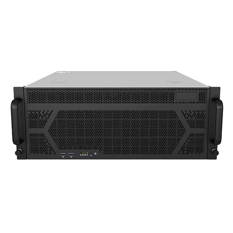
IStoneCase builds chassis for exactly this kind of work: GPU/server cases, NAS storage chassis, and custom OEM/ODM builds for data centers, algorithm centers, enterprises, MSPs, and dev teams. When you spec a chassis, you’re not just buying steel. You’re buying fewer “why doesn’t it boot” calls.
Here’s the argument: front panel discipline is the fastest way to cut operational pain while keeping your SKU lineup flexible.
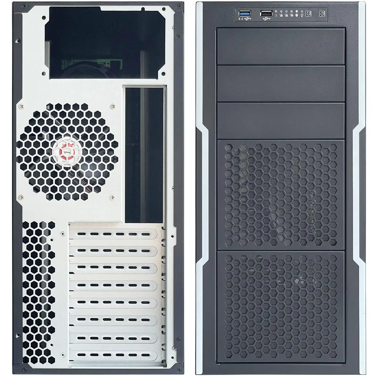
Standard Front Panel I/O Cutout for OEM ITX Appliances
Start with the cutout. Not the ports.
A lot of teams do it backwards: “We need 2x USB-A + 1x USB-C + reset + LEDs, so let’s draw holes.” Then they add a new SKU. Suddenly the hole pattern changes. Now the whole sheet metal needs rework, new tooling, new drawings, new QC checks. Your NPI timeline gets… spicy.
Instead, lock a standard front-panel I/O opening that can host different connector mixes. Think of it like a universal “window.” Inside that window, you can swap in different port clusters per model. That gives you:
- cleaner ECOs
- faster SKU spins
- fewer wrong parts in assembly (yep, that happens)
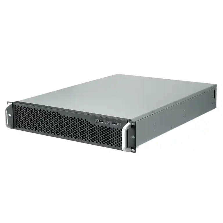
If you’re already shipping rack gear, the same thinking applies across families, from a compact server rack pc case to edge boxes and ITX appliances.
Practical scene:
You sell an edge gateway to two customers. One wants dual LAN + USB-C. One wants dual LAN + USB-A only. If your cutout is standardized, you swap the internal bracket or PCB. If it’s not standardized, you’re rebuilding the front panel each time. That’s pain you don’t need.
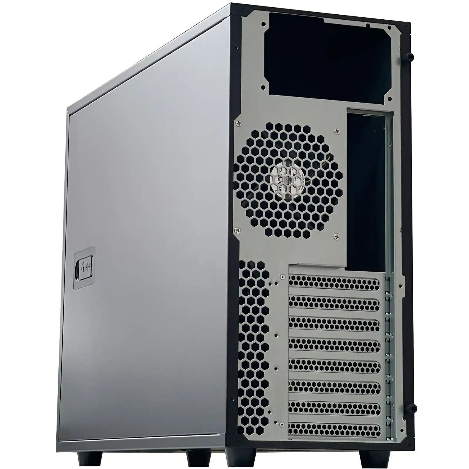
Keep-out Zone and EMI Grounding Around Front Panel I/O
Here’s a boring truth that saves your team later: the area around the cutout matters as much as the hole.
You need a keep-out zone so connectors seat right, cables don’t bind, and the panel doesn’t turn into an EMI leak. EMI issues are sneaky. The unit passes in the lab. Then it fails in a noisy plant with VFD motors. Now you’re chasing ghosts.
What to do:
- leave clean clearance around the opening (don’t crowd it with snaps, ribs, random standoffs)
- keep grounding surfaces consistent (paint in the wrong place can hurt contact)
- treat the port area like a “seal,” not a sketchpad
Real talk: a front panel that “looks fine” can still be a little RF antenna. It’s annoying. It’s also avoidable.
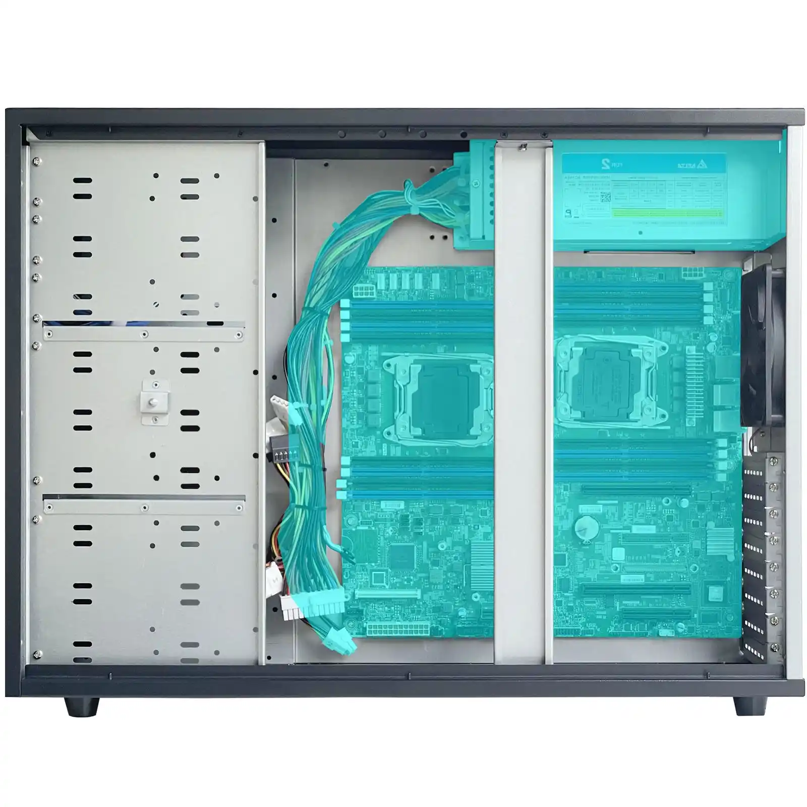
PCB-to-Chassis Offset and Clearance for I/O Layout
Most mechanical failures aren’t dramatic. They’re just… off by a couple millimeters.
If your I/O board sits too close to the wall, the connector can’t fully mate. If it sits too far, your button caps feel mushy. If your motherboard edge clearance is tight, the assembly tech has to “persuade” the board into place. That’s how cracked solder joints happen.
This is where you want boring, repeatable spacing rules:
- give the I/O side a predictable offset so shield/bracket parts fit
- keep enough side clearance so cables and hands can actually work
- plan for tolerance stack-up (metal bends, powder coat thickness, connector variance)
If you also do rack deployments, rails amplify these issues. A chassis that’s hard to service becomes a downtime machine. Pair the chassis with proper Chassis guide rail options so techs can slide, swap, and move on.
Power Button, Status LED, and Storage Activity LED on the Front Panel
If your appliance has no clear status, users will invent their own diagnostics. Usually by power-cycling it 9 times. That’s not a joke, it’s a pattern.
At minimum, front panel needs:
- power button that feels solid
- power/status LED that’s visible in bright rooms
- storage/activity LED (or a meaningful “heartbeat”)
- optional reset, but only if you truly need it (reset buttons cause accidents)
Scenario that happens a lot:
A remote hands tech stands in front of a rack at 2am. They see ten identical boxes. They need the right one. If your LEDs and labeling don’t help, they’ll yank the wrong cable. Then your incident channel lights up.
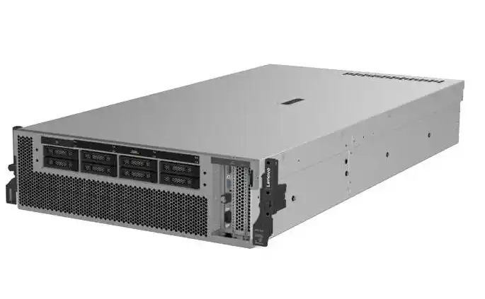
This matters whether you’re building an edge ITX appliance or a full-size server pc case. The front panel is your “fast debugging surface.”
Durable Labeling Methods for Front Panel Design
Labeling isn’t a branding sticker. It’s part of the UX.
Bad labels create classic failure modes:
- user plugs into the wrong port
- tech flips the wrong switch
- someone covers vents with a label (yes, really)
For OEM ITX appliances, you usually want one of these approaches:
- printed overlay + protective layer (clean look, good durability)
- laser etch (tough, but design changes cost time)
- high-quality industrial sticker (fast iteration, just don’t cheap out)
Your labeling should survive:
- rubbing from fingers and tools
- cleaning wipes
- heat
- shipping scuffs
Also, keep text simple. Use icons. Use arrows. Don’t make people guess.
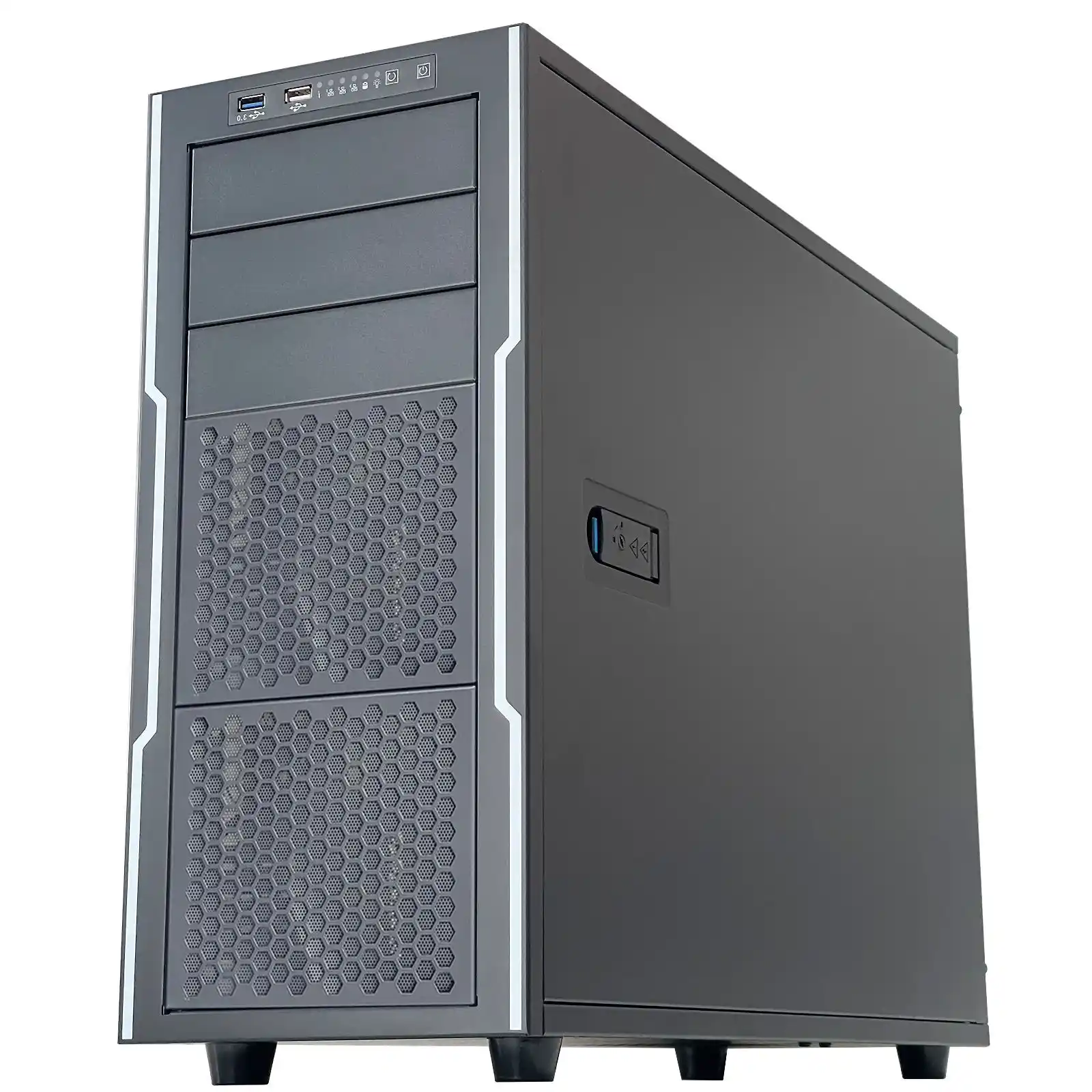
If you’re building storage boxes, labeling gets even more important. Drive bays, hot-swap mapping, and “don’t pull this” indicators reduce human error. This shows up in NAS gear like computer case server builds where one wrong pull can break an array. Not fun.
Regulatory Labels: FCC Part 15 and Country-of-Origin Marking
I’m not gonna drown you in legal text, but you do need to plan space for compliance labels early. If you don’t, you’ll end up slapping a random label on the worst possible surface. Then it peels. Then QA fights with operations. Then everyone loses.
Two common label buckets:
- EMC/Radio compliance statements (varies by product type and market)
- country-of-origin marking for import/export flows
This isn’t “optional paperwork.” It’s part of shipping. Make the label area intentional, flat, and readable. Leave enough room so it doesn’t look like an afterthought. Your buyers and inspectors notice.
Vent Pattern and Airflow Path for ITX Appliance Thermals
Please don’t do “hole art.” Do airflow.
A good ITX appliance behaves like a tiny wind tunnel:
- intake where air is clean
- exhaust where hot air leaves fast
- minimal recirculation
- no blocked fan paths by cables or brackets
Random vents can actually make cooling worse. They create short-circuit airflow where air takes the easy path and skips hot components.
Quick scene:
Edge box in a dusty workshop. If your intake isn’t filtered or the vent pattern invites dust piles, the fan turns into a vacuum cleaner. Temps climb. Performance droops. Then users say your software is “unstable.” It’s not. It’s choking.
If you’re going bigger, the same airflow logic scales into an atx server case or a GPU server case, just with louder consequences when cooling fails.
Design Rule Table for Labeling, I/O Layout, and Front Panel Design
| Item | What to standardize | Typical value / rule-of-thumb | Why it helps | Origin |
|---|---|---|---|---|
| Front panel I/O opening | A “universal window” for port clusters | ~98.4 mm × 25.4 mm class opening | Faster SKU swaps, fewer sheet-metal ECOs | Common front I/O geometry |
| Keep-out zone | Clear area around cutout | ≥ 2.5 mm around opening | Better connector seating, fewer EMI leaks | DFM + EMI practice |
| PCB-to-wall offset | I/O PCB sits predictably | ~1.6 mm class offset | Prevents “almost fits” assembly failures | Enclosure fit-up norm |
| Side clearance | Board edges vs chassis walls | ≥ 6 mm per side where possible | Easier assembly, less stress on boards | Practical assembly rule |
| LED visibility | Status LED placement | direct line-of-sight, no deep recess | Faster triage in racks/closets | Ops-driven UX |
| Label durability | Surface + print method | overlay/etch/sticker with wipe resistance | Fewer mis-plugs, fewer “what port is this” | Field service reality |
| Vent strategy | Air path, not random holes | front-to-back or side-to-side, consistent | Lower thermal risk, less dust chaos | Thermal design basics |
(Values are practical targets, not sacred. Your connector vendor and chassis build will tweak them.)
Where IStoneCase fits in OEM/ODM execution
When you build for scale, you want predictable mechanics. IStoneCase’s catalog gives you a starting point across form factors—ITX, rackmount, wallmount, GPU chassis, NAS, rails—and the OEM/ODM path lets you tune the front panel the way your product needs. That includes port layouts, button feel, labeling approach, and service-friendly details that keep MTTR down.
If your buyer cares about uptime, they care about these “small” choices. And if you ship in bulk, small mistakes don’t stay small. They multiply fast.