Sprechen Sie mit unserem Server-Gehäuse Ingenieure und Vertriebsteam
24.000 Abonnenten
Teilen Sie uns Ihre Anwendungsanforderungen, den Gehäusetyp, die Rackhöhe, das Motherboard, die GPU, die Laufwerksschächte, das Netzteil, die Kühlung, die E/A-Anschlüsse und die Bestellmenge mit. Unsere Ingenieure und unser Vertriebsteam werden Ihnen ein Standardmodell oder eine OEM/ODM-Konfiguration für Ihr Projekt empfehlen.
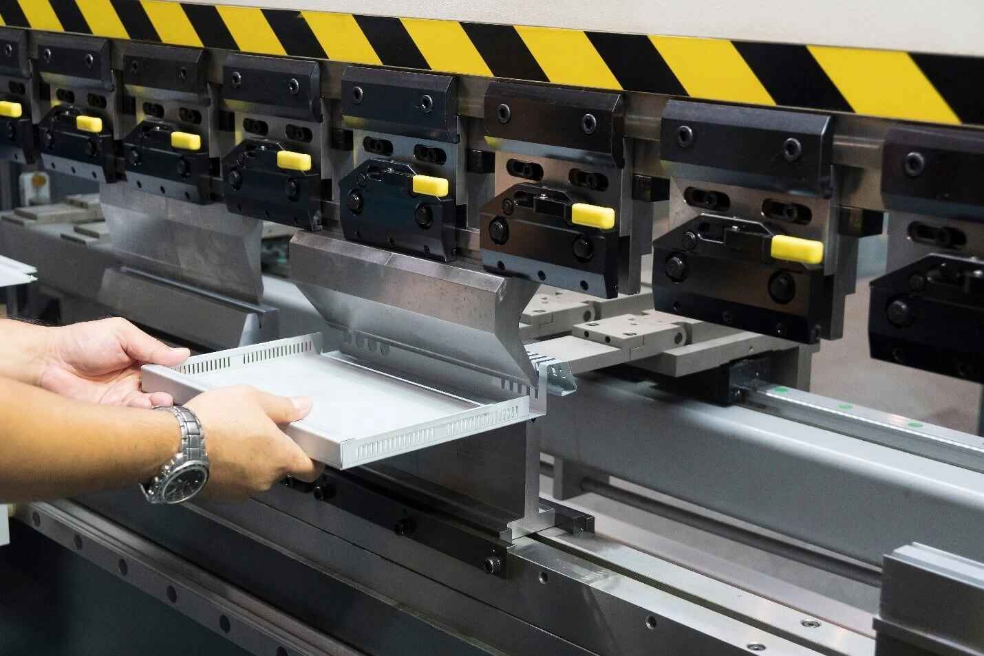
Picking sheet metal thickness for a server chassis looks easy until the first prototype reaches the assembly bench.
0.8 mm? 1.0 mm? 1.2 mm? Maybe 1.5 mm because “thicker is stronger.”
That is the wrong question.
Thickness changes everything.
A seemingly minor increase from 1.0 mm to 1.2 mm changes material consumption by only 20%, yet for an otherwise identical flat plate, basic plate theory predicts roughly a 72.8% increase in bending stiffness because stiffness scales with the cube of thickness, not linearly.
So why are chassis specifications still being approved by somebody pointing at a gauge chart?
I would never choose server chassis sheet metal thickness from thickness alone. I would start with the load path: rack ears, motherboard tray, drive cages, GPU supports, power supplies, rails, fan walls, cable loads, shipping loads, and the bends that connect them.
The answer is usually not “make everything thicker.”
It is put material where the load actually goes.
What Sheet Metal Thickness Should a Server Chassis Use?
For most rackmount designs, there is no single best sheet metal thickness for a server chassis. Different panels perform different jobs, so using one thickness everywhere can increase weight and fabrication cost without fixing the parts that actually flex.
As an engineering starting point—not a universal standard—I would investigate ranges like these:
Chassis Area
Practical Starting Range
What I Would Check
Cosmetic top cover
0.8–1.0 mm steel
Panel vibration, fastening points, removal frequency
Side panels
0.8–1.2 mm steel
Panel span, vents, bends, screw spacing
Motherboard tray
1.0–1.2 mm steel
Standoff loads, CPU cooler load, flatness
Main chassis floor
1.0–1.5 mm steel
PSU, GPU, drive and shipping loads
Front/rear structural panels
1.0–1.5 mm steel
Connector loads, rack alignment, cutout density
Drive cage
0.8–1.2 mm steel
Drive mass, vibration, hot-swap cycles
GPU support structure
1.2–2.0 mm steel or reinforced design
GPU mass, transport shock, retention method
Rack ears / mounting brackets
1.5–2.0+ mm steel
Cantilever load, rail interface, rack mounting
Aluminum chassis panels
Often thicker than comparable steel
Lower modulus, alloy, bends, ribs, fasteners
These numbers are design starting points, not automatic production specifications.
A 1.0 mm panel with two properly placed return flanges may outperform a poorly supported 1.5 mm flat panel. A 1.2 mm motherboard tray with beads or formed ribs can also be far stiffer than a featureless thicker sheet.
That is why I recommend defining the system requirements before CAD. Your chassis dimensions, motherboard, GPUs, storage, power architecture, mounting method and transportation conditions should already be locked through a process similar to the site’s key design inputs for a custom chassis project before somebody assigns material thicknesses to parts.
The Physics Buyers Usually Miss: Thickness Does Not Add Stiffness Linearly
This is where the discussion gets interesting.
MIT’s FUNdaMENTALS of Design gives the plate bending stiffness relationship:
D = Et³ / [12(1 − ν²)]
where:
D = plate bending stiffness
E = Young’s modulus
t = material thickness
ν = Poisson’s ratio
The important piece is t³.
MIT specifically notes that plate stiffness is proportional to the cube of thickness and also points out that folded edges and raised features can stiffen a plate without simply adding large amounts of material. MIT FUNdaMENTALS of Design — Structures
Consider a simplified comparison where geometry, material and boundary conditions remain unchanged:
Thickness
Relative Material Mass
Relative Plate Stiffness
1.0 mm
1.00×
1.00×
1.2 mm
1.20×
1.73×
1.5 mm
1.50×
3.38×
2.0 mm
2.00×
8.00×
That is not a typo.
Moving from 1.0 mm to 1.2 mm adds 20% thickness but theoretically increases plate bending stiffness by about 72.8%.
Going from 1.0 mm to 1.5 mm adds 50% material thickness but increases plate stiffness to about 3.375 times the original value.
Of course, a real server chassis is not an isolated mathematical plate. Cutouts, bends, spot welds, screws, PEM fasteners, ventilation perforations, seams and mounting boundaries all alter the result.
But this mathematical relationship explains something I see repeatedly in chassis design logic: a manufacturer does not necessarily need another millimeter of metal. Sometimes another 0.2 mm in the right component is enough.
Geometry Can Beat Thickness
This is one of the hard truths buyers should understand.
Sheet metal engineers have other tools:
Return flanges
Hemmed edges
Embossed ribs
Stiffening beads
Hat sections
Box sections
Cross members
Local reinforcement plates
Shorter unsupported spans
Additional fastening points
MIT’s plate-design material explicitly notes that folded edges and raised plate features can increase stiffness without greatly increasing weight.
So when somebody tells me, “Our competitor uses 1.2 mm, therefore we need 1.2 mm,” my response is simple:
Show me the geometry first.
SPCC Steel Thickness: The Grade Does Not Tell You the Thickness
This causes a surprising amount of confusion in RFQs.
SPCC is not a thickness.
JIS G 3141 covers cold-reduced carbon steel sheet and strip, and the published 2017 standard text identifies SPCC as a commercial-use grade with an applicable thickness range rather than one fixed dimension. Its listed preferred standard thicknesses include values such as 0.8, 0.9, 1.0, 1.2, 1.4, 1.6, 1.8 and 2.0 mm.
That distinction matters.
“SPCC chassis” tells me something about the material category.
“1.2 mm SPCC” tells me substantially more.
And a production drawing should go further by defining the applicable material specification, nominal thickness and allowable thickness tolerance.
If your RFQ simply says “SPCC steel chassis,” two suppliers can legitimately quote structures with very different mass and rigidity.
SPCC, SGCC and Aluminum Should Not Be Compared by Thickness Alone
A 1.2 mm aluminum panel is not structurally equivalent to a 1.2 mm steel panel.
MIT’s representative material data places the Young’s modulus of carbon/low-alloy steel around 193–220 GPa, while aluminum materials are approximately 68–79 GPa. The same table gives density ranges around 7.73–7.87 × 10³ kg/m³ for steel und 2.66–2.89 × 10³ kg/m³ for aluminum. MIT material modulus and density data
That creates an interesting engineering trade-off.
Steel is roughly three times as stiff by Young’s modulus, but aluminum is roughly one-third the density.
In a simplified plate calculation, an aluminum plate may need to be around 1.4 times as thick as steel to approach the same bending rigidity, depending on the actual alloys and geometry. Even after increasing thickness, the aluminum version may still weigh substantially less.
This is why aluminum chassis thickness often looks excessive to somebody accustomed to steel.
It is not necessarily excessive.
The material behaves differently.
A U.S. National Highway Traffic Safety Administration structural research program provides another useful reality check: several aluminum grades in its lightweight-structure models use approximately 2,700 kg/m³ density and 71 GPa modulus of elasticity. NHTSA Structural Countermeasure Research Program
Where Server Chassis Material Thickness Actually Matters
A server chassis is not loaded evenly.
That is why I divide the enclosure into load zones.
1. Rack Ears and Front Mounting Structure
Rack ears look small, but they can carry ugly loads.
If the chassis is partially cantilevered during installation, the front mounting structure may see substantial bending before the rails are fully engaged. Repeated installation also works screws, slots and bends.
I would rather reinforce a rack ear locally than increase the entire chassis from 1.0 mm to 1.5 mm.
2. Chassis Floor
The floor often carries:
Motherboard assemblies
GPU brackets
Power supplies
Drive cages
Fan partitions
Cable assemblies
Internal supports
A long 4U chassis with a heavily perforated bottom panel behaves differently from a compact 1U appliance even when both are made from identical 1.0 mm steel.
Span matters.
So does where the bends are.
3. GPU Support Zones
Modern accelerator systems expose weak chassis designs quickly.
Large PCIe cards do not merely add static weight. Shipping creates acceleration loads, and those forces can act through card brackets, motherboard slots and retention structures.
If the design contains heavy accelerators, I would treat GPU retention as a structural problem, not an accessory decision. The related guide on how GPU retention brackets improve system stability explains why retention geometry matters alongside the sheet metal carrying it.
A thick floor with a weak GPU bracket is still a weak GPU system.
4. Drive Cages
Storage chassis create another problem: repeated mass.
One hard drive is manageable.
Twelve, twenty-four or sixty drives are not.
The cage itself, the mounting rails, the backplane support and the chassis floor must work as one structure. And vibration makes excessive compliance even less attractive.
5. PSU Mounting Areas
A redundant power-supply cage can place concentrated loads around a relatively small rear opening.
Large cutouts remove material exactly where engineers sometimes need stiffness.
This is another reason “1.2 mm chassis” tells me almost nothing unless I have seen the drawing.
Stop Specifying Server Chassis Sheet Metal by Gauge Alone
I am not a fan of vague gauge specifications.
The reason is historical as much as technical.
Gauge is not a universal physical unit.
Even the U.S. legal table for sheet and plate iron and steel assigns specific physical dimensions to gauge numbers. Under 15 U.S. Code §206, for example, U.S. Standard Gauge lists:
Then thermal engineering covers 60% of it with perforations.
Now you have a different structure.
Large fan cutouts, honeycomb ventilation, PCIe openings, PSU windows, cable apertures and drive bays remove load-carrying material. The remaining ligaments around those openings may twist or vibrate even if the nominal server chassis material thickness never changed.
And simply increasing thickness may create another problem: unnecessary obstruction or packaging compromises.
This matters even more in 1U and 2U systems, where millimeters are expensive.
A Better Method for Choosing Sheet Metal Thickness
I use a much more disciplined sequence.
Step 1: Define the Hardware Mass
List the mass and mounting position of:
Hauptplatine
CPU coolers
GPUs
PSUs
HDDs/SSDs
Backplanes
Fans
Liquid-cooling hardware
Schiene
Cable assemblies
Do not rely only on total chassis weight.
A 4 kg load concentrated 400 mm from its support can matter more than several kilograms sitting directly above a structural member.
Step 2: Map the Load Path
Ask where every heavy component transfers force.
GPU → retention bracket → floor?
PSU → rear cage → sidewall?
Drive cage → crossmember → chassis floor?
Rack chassis → rail brackets → rack posts?
If you cannot draw that path, you are not ready to finalize sheet thickness.
Step 3: Measure Unsupported Spans
Large flat panels flex.
Reduce the span and the problem often becomes easier.
Before making a 1.0 mm floor 1.5 mm thick, I would ask whether a formed rib, crossmember or return flange could solve the same problem with less weight.
Step 4: Account for Cutouts
Do the structural review using the actual production geometry, not a solid rectangular plate.
Fans, drive slots and connectors matter.
Step 5: Check Local Fastener Loads
PEM nuts, screws, standoffs and rivets concentrate loads.
Very thin metal can deform around the fastener long before the entire panel looks overloaded.
Step 6: Check Manufacturing
The design needs to bend, punch, weld and assemble predictably.
That means thickness selection should be reviewed during DFM, not after the drawings have already been released.
Step 7: Build the Prototype
This is where theory meets reality.
The site’s CAD-to-production prototype workflow already emphasizes DFM, tolerance control, testing and revision before production handoff. That is exactly where sheet thickness assumptions should be challenged.
Load it.
Lift it.
Rack it.
Populate it.
Ship-test it if transportation risk warrants it.
Open the cover repeatedly.
Measure deflection around rails, GPU brackets and PSU openings.
Listen for vibration.
A prototype that merely “fits” has not proven structural adequacy.
Do Not Let the Factory Quietly Change Thickness
This deserves its own section because procurement teams sometimes underestimate it.
Suppose the approved prototype uses:
1.2 mm SPCC
Then production begins and a material substitution turns that into:
1.0 mm
The material reduction is about 16.7% in thickness.
But under the simplified t³ plate relationship, relative bending stiffness falls from:
1.2³ = 1.728
to:
1.0³ = 1.000
That is roughly a 42% reduction in bending stiffness relative to the 1.2 mm plate.
A buyer looking only at the 0.2 mm dimensional change might completely miss what happened structurally.
This is why material thickness belongs in controlled drawings and BOM revisions. If production requires a change, run it through the same type of engineering change control process before production used for other design changes.
“No functional change” is not an acceptable assumption.
Prove it.
What I Would Put on the Chassis Drawing
For a production-ready server chassis, I would want the drawing or specification to make the material requirement difficult to misinterpret.
At minimum, identify:
Material grade
Material standard
Nominal thickness in mm
Applicable thickness tolerance
Temper where relevant
Coating or plating requirement
Oberflächengüte
Grain direction where forming makes it relevant
Critical flatness requirements
Bend requirements
Revision level
For inspection, thickness should also be measurable.
If the incoming sheet is specified as 1.2 mm, your inspection plan needs a defined acceptance criterion rather than somebody deciding visually whether it “looks thick enough.”
That sounds obvious.
Production disputes often begin with things that sounded obvious.
My Rule for the Best Sheet Metal Thickness for a Server Chassis
There is no universal magic number.
For many steel server chassis, 0.8–1.2 mm can make sense for covers and secondary panels, 1.0–1.5 mm for more structural chassis members, and thicker local reinforcements for rack ears, heavy GPUs, PSUs or concentrated loads.
If somebody gives you a sheet metal thickness recommendation without asking about those variables, they are guessing.
Sometimes the guess works.
I would not build a production order around it.
FAQs
Was ist die optimale Blechdicke für ein Servergehäuse?
The best sheet metal thickness for a server chassis is the minimum thickness that satisfies structural stiffness, component loads, rack mounting, transportation, vibration, manufacturing and service requirements after the actual panel geometry, bends and cutouts are considered; many steel designs therefore use multiple thicknesses rather than one thickness throughout the enclosure.
Typical starting points range from about 0.8–1.2 mm for covers and secondary panels to 1.2–2.0 mm or more for locally load-bearing structures.
Is 1.0 mm steel thick enough for a server chassis?
A 1.0 mm steel sheet can be thick enough for many server chassis panels when unsupported spans are short, bends and ribs provide stiffness, hardware loads are moderate, cutouts do not remove excessive material, and heavier components such as GPUs, PSUs and rack interfaces receive separate structural reinforcement where required.
I would not approve 1.0 mm solely because another chassis uses it; the geometry and load path need to be reviewed.
Is 1.2 mm sheet metal much stronger than 1.0 mm?
A 1.2 mm plate can be substantially stiffer in bending than a geometrically identical 1.0 mm plate because classical plate stiffness scales approximately with thickness cubed; under the same simplified material and boundary assumptions, increasing thickness from 1.0 to 1.2 mm raises calculated bending stiffness by roughly 72.8%.
Real chassis results vary because bends, holes, fasteners, ribs and boundary conditions change the structural behavior.
What SPCC steel thickness should be used for a server chassis?
SPCC steel thickness for a server chassis should be selected independently from the SPCC material designation, because SPCC identifies a commercial cold-rolled steel category under JIS G 3141 rather than one fixed thickness; chassis designers should specify the required nominal thickness explicitly according to each panel’s structural function.
Common chassis designs may use several SPCC thicknesses, such as 0.8, 1.0, 1.2, 1.5 or similar production-appropriate dimensions.
Is aluminum chassis thickness the same as steel chassis thickness?
Aluminum chassis thickness should not be selected by directly copying a steel thickness because aluminum has a much lower Young’s modulus than steel, although it also has substantially lower density; equivalent structural performance therefore usually requires different thickness, geometry, alloy selection, reinforcement and fastening decisions.
For the same simplified plate bending rigidity, aluminum may need to be noticeably thicker while still offering a substantial weight advantage.
Should I specify sheet metal thickness in gauge or millimeters?
Sheet metal thickness for an internationally manufactured server chassis should preferably be specified as an explicit physical dimension such as millimeters, together with the material and applicable standard, because gauge numbers can correspond to different thickness conventions and therefore introduce avoidable ambiguity between engineering drawings, suppliers and inspection teams.
Gauge can remain a secondary reference, but I would not make it the only production thickness definition.
Does thicker sheet metal always make a better server chassis?
Thicker sheet metal does not automatically produce a better server chassis because excessive thickness increases material use, weight, bending force and potentially fabrication cost while doing little to correct poorly located supports, weak rack ears, long unsupported spans, inadequate GPU retention or structural material removed by large ventilation openings.
Good geometry is often a more efficient solution than simply adding metal everywhere.
Build the Thickness Specification Before You Release the RFQ
Do not send a chassis supplier a drawing that says only “steel enclosure” oder “18 gauge.”
Define the hardware loads. Identify the structural zones. Select the material. Specify thickness in millimeters. Review the bends and perforations. Prototype the assembly. Then freeze the approved configuration under revision control.
If you are developing a custom 1U, 2U, 4U, GPU, storage or industrial rackmount chassis, send the manufacturer your motherboard drawing, GPU and PSU configuration, storage layout, rack dimensions, expected system weight and target material requirements.
Ask the engineering team to review sheet metal thickness before tooling or volume production begins—not after the first production batch starts flexing.
Mark Lee - Founder & Server Chassis OEM/ODM Specialist
Mark Lee is the founder of ISTONECASE, with 20 years of experience in the server chassis industry. He specializes in OEM/ODM solutions for GPU and AI, rackmount, industrial, wallmount, NAS, Mini-ITX and multi-node chassis. His expertise supports customized hardware projects for data centers, AI computing, enterprise storage, edge computing, networking and industrial applications.