Contactez notre Châssis de serveur Ingénieurs et équipe commerciale
24 000 abonnés
Indiquez-nous votre application, le type de châssis, la hauteur du rack, la carte mère, la carte graphique, les baies de disques, l'alimentation, le système de refroidissement, les ports d'E/S et la quantité commandée. Nos ingénieurs et notre équipe commerciale vous proposeront un modèle standard ou une configuration OEM/ODM adaptée à votre projet.
When a buyer sees “CRPS compatible” beside a server chassis and “CRPS” beside a 2,400 W power supply, it is tempting to treat those two labels as a mechanical and electrical guarantee, even though width, depth, connector position, PDB architecture, input-voltage derating, firmware communication, airflow direction, latch geometry, and redundancy design can still disagree.
So what exactly have you proved?
Not much.
That is the uncomfortable answer.
CRPS—Common Redundant Power Supply—exists specifically to reduce the chaos that once surrounded proprietary redundant server power supplies. The Open Compute Project’s DC-MHS work now includes M-CRPS specifications intended to create consistent power-supply interfaces for modular server platforms. OCP’s published documentation includes the M-CRPS 1.05 RC5 specification submitted on October 1, 2024, together with an October 2024 M-CRPS design-specification release package.
Standardization helps enormously.
But standardized does not mean universal.
And that distinction is where expensive chassis mistakes begin.
What CRPS Power Supply Compatibility Actually Means
I use a stricter definition than the one I often see on purchasing spreadsheets.
A server chassis is genuinely compatible with a CRPS power supply only when the entire installed power subsystem works together:
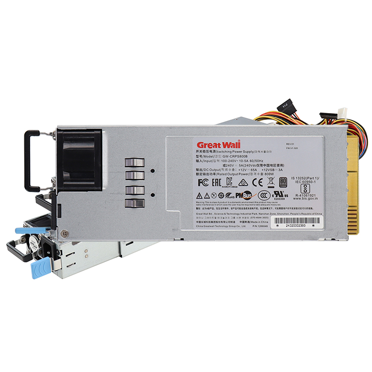
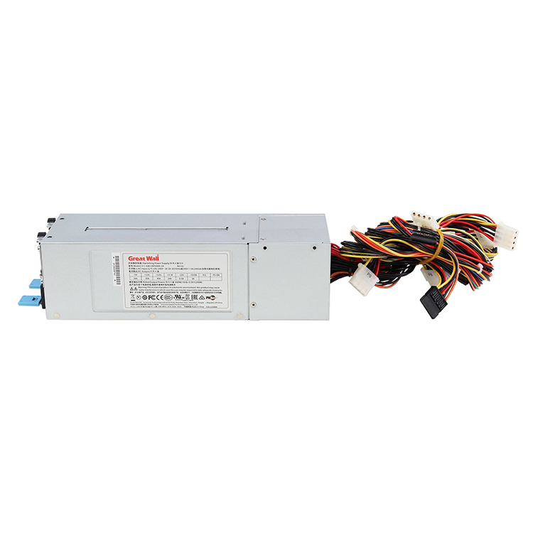
PSU mechanical envelope
PSU insertion path
retention latch
output card-edge connector
mating connector
CRPS power distribution board
+12 V main output
standby-power architecture
PMBus/SMBus signals
current-sharing system
redundancy mode
AC or DC input
input connector
airflow direction
PSU exhaust clearance
hot-swap access
cable routing
motherboard/GPU power distribution
system peak load
rack input voltage
Miss one and the chassis can fail even though both product descriptions contain the letters “CRPS.”
This is why I would never approve a custom server enclosure from a line in an RFQ that says simply:
Power Supply: 2 × CRPS
That is not an engineering specification.
It is a clue.
Before chassis CAD is frozen, the PSU should be treated like the motherboard, GPU, backplane, fan wall, and drive cage: a defined mechanical and electrical component. The same principle appears throughout our guidance on the key design inputs for a custom chassis project—design around the final hardware architecture rather than vague component categories.
The First Trap: “CRPS Form Factor” Is Not One Number
Here is where the assumption becomes dangerous.
Many widely used M-CRPS supplies follow a compact envelope around 40 mm high × 73.5 mm wide × 185 mm deep. Advanced Energy, for example, currently lists its 2.4 kW CSU2400AT M-CRPS supply at 1U × 73.5 × 185 mm, with up to 196.7 A output and peak efficiency of 96%.
Easy, right?
No.
HPE’s current Modular Common Redundant Power Supply documentation lists two M-CRPS widths: 73.5 mm and 60 mm. HPE also explicitly states that its new M-CRPS design is not compatible with servers prior to Gen12.
Read that again.
Two products can legitimately be described in the market as M-CRPS while still demanding different mechanical provisions at chassis level.
That single fact destroys the lazy buying rule:
“CRPS is CRPS.”
It isn’t.
Dimensions I Would Put on the Approval Drawing
Do not request only PSU length, width, and height.
Request:
body width;
body height;
PSU insertion depth;
connector engagement depth;
handle protrusion;
latch position;
rear stop location;
mating-connector datum;
installation tolerance;
required insertion clearance;
extraction clearance;
airflow inlet and outlet zones.
For a standard server chassis, millimeters matter.
For a 1U system, they matter even more.
If chassis height is still being selected, review the thermal and mechanical tradeoffs in 1U vs 2U vs 4U server chassis form factors before locking the PSU architecture. A power subsystem that is easy to package in 4U may become ugly very quickly in 1U.
The PDB Is Where “Almost Compatible” Systems Go to Die
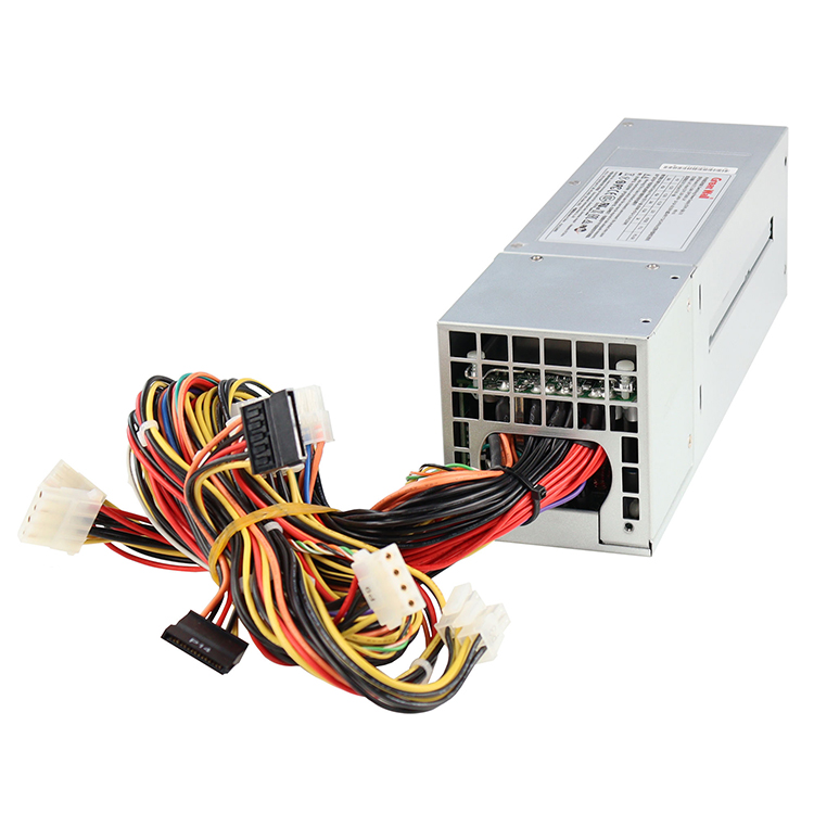
A CRPS PSU usually does not behave like a consumer ATX power supply with a bundle of motherboard connectors hanging from it.
The server architecture commonly places a Power Distribution Board, or PDB, between the redundant PSU modules and the downstream motherboard, storage, GPU, fan, or auxiliary power loads.
That board matters.
A lot.
The CRPS modules may provide high-current 12 V power and standby power through a card-edge interface. The PDB then becomes responsible for distributing that power through the system and, depending on the architecture, providing additional conversion, protection, sensing, management, or output connectors.
So when a supplier tells me:
“Yes, our chassis accepts CRPS.”
My next question is:
Which PDB?
If the answer is vague, the compatibility review is unfinished.
What to Check on the CRPS Power Distribution Board
Ask for:
PDB part number or drawing.
CRPS mating connector specification.
Supported CRPS revision or PSU family.
Maximum continuous 12 V current.
Peak-current capability.
Number of supported PSU modules.
1+1, 2+1, N+1, or N+N redundancy support.
Current-sharing support.
Standby-power path.
PMBus/SMBus connections.
CPU power outputs.
GPU/PCIe power outputs.
motherboard power connectors.
fan and drive power outputs.
overcurrent protection.
copper thickness and busbar architecture.
thermal limits.
connector current rating.
cable-gauge requirements.
replacement availability.
This is where I become unpopular with vague quotations.
Good.
A $30 metal-panel change is inconvenient.
A power-board redesign after chassis tooling, prototype approval, cable production, and motherboard integration is much worse.
CRPS Power Supply Compatibility Checklist
Compatibility Item
What Must Match
Typical Failure
PSU width
Chassis cage and guide width
60 mm PSU specified for a 73.5 mm mechanical design
PSU depth
Internal envelope and connector location
PSU fits opening but cannot fully engage
Hauteur
Chassis vertical clearance
Interference in dense 1U packaging
Output connector
PSU and PDB mating interface
Physical insertion without electrical compatibility
PDB rating
System current and peak load
Connector or copper path overheats
PSU quantity
1+1, 2+1, N+1, N+N architecture
Redundancy disappears at full load
AC input
Site voltage versus rated output
“2,000 W” PSU provides much less power at low line
Main output
System distribution architecture
Incorrect voltage or downstream conversion
Standby supply
Motherboard/platform requirement
Management functions fail when system is off
PMBus/SMBus
Platform management support
PSU health or telemetry unavailable
Débit d'air
Chassis front-to-rear cooling path
PSU fights system airflow
Hot-swap clearance
Rack and rear service area
PSU technically removable only after disconnecting other hardware
Power cord inlet
C14/C20 or other inlet and cable
Wrong rack PDU or cable selected
Efficiency/compliance
Deployment market requirements
Finished server misses procurement or regulatory target
I would attach a version of this table to every serious chassis RFQ.
For custom projects, our complete chassis RFQ guide provides a broader framework for locking drawings, components, tolerances, quantities, inspection requirements, and production assumptions before quotations are compared.
A 2,000 W CRPS PSU May Not Give You 2,000 W
This one catches buyers because the product name itself feels authoritative.
Imagine the BOM says:
2 × 2,000 W CRPS PSU
Someone enters 4,000 W into a spreadsheet.
Done.
Except the rack operates on a voltage at which the selected PSU cannot provide its full advertised output.
A current Lite-On 2,000 W CRPS example illustrates the problem beautifully. Its published data lists:
90–132 Vac: 1,000 W
180–200 Vac: 1,600 W
201–220 Vac: 1,800 W
221–264 Vac: 2,000 W
The same PSU also lists a 73.5 × 40 × 185 mm enclosure and a 12.2 V high-line output reaching roughly 163.5 A.
This is not a minor specification detail.
At low-line input, the nominal “2,000 W” unit in this example becomes a 1,000 W source.
Half.
Now imagine a GPU server that was sized under the assumption that each PSU would deliver 2 kW regardless of facility input.
Would you want to discover that after the machines arrive?
Always Calculate Power at the Real Facility Input
The RFQ should state:
100–120 Vac?
200–240 Vac?
208 Vac?
230 Vac?
240 Vac?
277 Vac?
high-voltage DC?
-48 Vdc telecom input?
Then request the PSU’s rated output at that exact input range.
Do not use only the model number’s headline wattage.
And do not confuse aggregate PSU nameplate power with fault-tolerant system power.
Redundant Does Not Mean Double the Usable Power
This misunderstanding refuses to die.
Two 2,000 W power supplies installed side by side do not automatically mean a 4,000 W fault-tolerant server.
If the system is designed as 1+1 redundancy, either supply should be capable of carrying the required system load after the other PSU fails or is removed.
That changes the math completely.
Suppose:
PSU A = 2,000 W available at the facility input;
PSU B = 2,000 W;
server sustained maximum = 1,700 W.
In a properly engineered 1+1 design, losing one PSU still leaves enough capacity.
Now suppose the server can demand 2,700 W.
Both supplies may carry that load together under normal conditions, but one 2,000 W module cannot maintain it after a failure.
You have parallel power.
You do not have full 1+1 redundancy at 2,700 W.
That distinction belongs in the purchasing specification.
Ask What Happens After One PSU Fails
I care more about this number than the giant wattage printed on a product page:
Maximum supported system load with one PSU unavailable.
That is the number that tells me whether the claimed redundancy actually survives the failure scenario the buyer thinks it survives.
Then repeat the calculation under the intended degraded PSU state.
Power Density Is Rising, So Small Compatibility Errors Cost More
This discussion is becoming more important, not less.
The U.S. Department of Energy’s Lawrence Berkeley National Laboratory published a 2025 update in June 2026 estimating that data centers could account for 11.8% of total U.S. electricity use by 2030, with modeled scenarios ranging from 9.5% to 15.3%.
The earlier DOE-backed 2024 report estimated 176 TWh of U.S. data-center electricity consumption in 2023 and projected 325–580 TWh by 2028.
That macro number matters at chassis level because dense AI and accelerated-computing systems keep pushing more current through smaller mechanical spaces.
The metal box is not passive anymore.
Its layout determines:
PSU density;
airflow resistance;
PDB cooling;
cable length;
connector temperature;
GPU power routing;
fan placement;
hot-swap access;
serviceability.
For high-power accelerator projects, I would review the power subsystem together with the available GPU and AI server chassis architectures rather than treating the PSU as something added after the enclosure is chosen.
Efficiency Is Now a Procurement and Regulatory Question
Another habit I dislike: choosing a CRPS PSU entirely by peak wattage.
Efficiency matters because every watt lost in the PSU becomes heat that the cooling system has to remove.
There is also a compliance angle.
For covered servers and online data-storage products placed on the EU market, Commission Regulation (EU) 2019/424 establishes minimum PSU efficiency requirements. From January 1, 2023, its table for single-output PSUs specifies minimum efficiencies of 90% at 10% load, 94% at 20%, 96% at 50%, and 91% at 100%, together with a minimum 0.95 power factor at 50% load. Scope and exemptions still need to be checked for the finished product.
That 50%-load figure is interesting.
Current high-end supplies can operate around that territory: Advanced Energy’s 2.4 kW M-CRPS product advertises peak efficiency of up to 96%.
But do not buy the badge and stop thinking.
Ask for the efficiency curve at your expected operating load.
A 3,200 W PSU running a lightly loaded appliance can make less sense than a smaller supply operating closer to its efficient zone, unless the larger unit is required for redundancy, peaks, future expansion, or platform standardization.
Check Airflow Before the Chassis Is Cut
The PSU fan is part of the server’s airflow system.
Not decoration.
If the chassis is designed for front-to-back airflow but the selected PSU moves air in the opposite direction, several ugly things can happen:
hot exhaust re-enters the chassis;
the PSU ingests preheated air;
local recirculation forms;
rear-component inlet temperature rises;
PSU fan speed increases;
acoustic noise increases;
PSU efficiency can decline;
component life may suffer.
And because the PSU often occupies a corner of the chassis, the problem can remain local enough that a CPU temperature test does not immediately expose it.
This is why power and thermal design belong in the same engineering review.
Our guide to designing front-to-back server chassis airflow explains how fan pressure, bypass air, drive cages, backplanes, cables, GPUs, and rear restrictions interact. Add the CRPS PSU to that same airflow map.
Ask for the Airflow Arrow
Literally.
Get the PSU drawing.
Find the airflow arrow.
Place it into the chassis CAD.
Then ask where the hot air goes.
This takes minutes.
Fixing the opposite condition after metal production takes longer.
PMBus, Monitoring, and Firmware Are Part of Compatibility Too
Mechanical compatibility gets the attention because it is visible.
Management compatibility often gets ignored until integration.
Many modern CRPS and M-CRPS platforms use PMBus/SMBus communication for functions such as:
PSU identification;
input-voltage monitoring;
output-current monitoring;
temperature monitoring;
fan-speed reporting;
warning flags;
fault reporting;
power-capability identification;
inventory information;
firmware functions.
Advanced Energy’s current 2.4 kW M-CRPS, for example, includes digital control over an I²C interface and PMBus support.
A PSU can therefore deliver 12 V successfully while the BMC still complains.
That is a compatibility failure too.
Maybe not on a bench.
Definitely in a managed server fleet.
So ask whether the motherboard/BMC expects specific PSU addressing, telemetry, firmware behavior, or platform identification.
Hot-Swap Only Matters If a Technician Can Reach the PSU
I have a simple test for “hot-swappable.”
Can a technician actually remove the failed CRPS module from the installed server without moving the rack, disconnecting unrelated cables, removing a PDU, or fighting a cable-management arm?
If not, I would hesitate to celebrate the feature.
Server serviceability has geometry.
Rear space may contain:
two AC power cables;
network connections;
management cables;
GPU/network expansion I/O;
a cable-management arm;
vertical rack PDUs;
liquid-cooling hoses;
strain-relief hardware.
Your CRPS module may need 185 mm of internal space but considerably more external space for extraction.
A rack can be deep enough for the chassis and still make PSU service miserable.
The CRPS Compatibility Review I Would Require Before Production
Before approving a server chassis, I would want this package.
Mechanical Evidence
Exact CRPS manufacturer and model
2D mechanical drawing
3D STEP model
PSU width
height
profondeur
handle geometry
latch location
card-edge location
insertion direction
insertion tolerance
extraction distance
Electrical Evidence
Rated output at actual site input voltage
main output voltage
maximum continuous current
peak-current capability
standby output
input connector
PDB schematic or interface drawing
PDB current rating
downstream connector list
cable gauges
protection architecture
Redundancy Evidence
PSU quantity
normal operating mode
1+1 / N+1 / N+N definition
maximum load after one PSU failure
current-sharing behavior
hot-plug support
fault response
Management Evidence
PMBus version
SMBus/I²C requirements
addressing
telemetry
BMC compatibility
PSU presence detection
alert/fault lines
firmware requirements
Thermal Evidence
PSU airflow direction
inlet-temperature range
output derating versus temperature
fan exhaust clearance
PDB temperature
cable/connector temperature
failed-fan or failed-PSU thermal behavior
Production Evidence
exact approved PSU model
exact approved PDB revision
alternate PSU policy
alternate PDB policy
BOM revision control
prototype validation
full-load test
redundancy test
hot-swap test
That last group saves projects.
A substitute PSU should not enter production merely because procurement found one with the same wattage.
The Most Dangerous Sentence in a Chassis Quotation
“Supports CRPS PSU.”
I dislike that sentence unless it is followed by a model list or an interface drawing.
Because what does “supports” mean?
The opening is the right size?
A PSU slides in?
The PDB mates?
The BMC recognizes it?
Both PSUs share load?
The system survives removal of one module?
Full output is available at 208 Vac?
The PSU can physically be extracted inside the target rack?
Those are seven different questions.
A professional quotation should tell you enough to answer them.
If you are buying a standard chassis, request the manufacturer’s validated CRPS PSU and PDB compatibility list.
If you are developing a custom server chassis, send the exact PSU and PDB drawings before the first mechanical layout is released.
That is the difference between “compatible on paper” and compatible in production.
FAQ
Qu'est-ce que la compatibilité des alimentations CRPS ?
CRPS power supply compatibility means that the selected PSU, server chassis, power distribution board, electrical interface, input voltage, redundancy architecture, airflow direction, management signals, and service clearances operate together as one validated power subsystem rather than merely sharing a CRPS label or similar external dimensions.
A proper review should therefore confirm exact model numbers and drawings rather than accepting “CRPS supported” as sufficient evidence.
Les blocs d'alimentation CRPS ont-ils tous la même taille ?
No, CRPS power supplies are not guaranteed to have one universal physical size, because current M-CRPS implementations can use different mechanical widths and platform-specific designs even when they follow related industry specifications; HPE, for example, currently documents both 60 mm and 73.5 mm M-CRPS widths.
Depth, latch location, connector datum, handle geometry, and chassis guide structure should still be checked against the exact PSU model.
Un bloc d'alimentation CRPS peut-il fonctionner dans n'importe quel châssis de serveur CRPS ?
No, a CRPS PSU cannot automatically be assumed to work in every chassis advertised as CRPS compatible, because the PSU and chassis must also agree on mechanical dimensions, card-edge connection, PDB interface, current capacity, standby power, communication signals, redundancy design, input-voltage requirements, cooling direction, and service access.
The safest purchasing method is to obtain a validated compatibility list or approve the PSU, PDB, and enclosure together.
What is a CRPS power distribution board?
A CRPS power distribution board is the intermediate server power assembly that receives high-current power from one or more redundant PSU modules and distributes it to the motherboard, processors, GPUs, storage, fans, and auxiliary devices while potentially handling protection, current sharing, monitoring, standby power, and downstream voltage conversion.
Its connector type and current rating should be treated as part of the chassis specification, not as a generic accessory.
How much CRPS power supply wattage does my server need?
The required CRPS power supply capacity is the maximum validated system demand—including CPUs, GPUs, memory, drives, fans, motherboard loads, expansion cards, conversion losses and transient margin—calculated at the actual facility input voltage and again under the intended failed-PSU condition if the server requires redundancy.
Do not calculate from advertised PSU wattage alone because some supplies deliver substantially less output at lower AC input voltages.
What is the best server chassis for a CRPS power supply?
The best server chassis for a CRPS power supply is one validated for the exact PSU and PDB configuration, with sufficient mechanical clearance, current capacity, front-to-rear airflow, hot-swap extraction space, motherboard and GPU power routing, rack depth, management compatibility, and redundancy capacity for the server’s maximum intended workload.
For OEM projects, I would prioritize documented compatibility and accessible engineering drawings over a generic claim that the enclosure “supports redundant power.”
What should I send a chassis manufacturer to verify CRPS PSU compatibility?
To verify CRPS PSU compatibility, send the chassis manufacturer the exact PSU manufacturer and model, mechanical drawing or STEP file, PDB specification, mating connector information, facility input voltage, system peak load, redundancy requirement, motherboard and GPU configuration, airflow direction, rack depth, management requirements, and expected production configuration.
The more completely those inputs are frozen before CAD begins, the lower the probability of redesign after prototyping.
Your Next Steps: Verify the Power System Before Approving the Chassis
Do not buy a server chassis because the product page contains the word CRPS.
Verify the system.
Send your chassis supplier:
exact CRPS PSU model;
PSU drawing or STEP file;
CRPS PDB model;
motherboard specification;
CPU configuration;
GPU quantity and power;
storage configuration;
actual rack input voltage;
required redundancy mode;
expected maximum system load;
airflow direction;
rack dimensions and rear service clearance.
Then request confirmation of mechanical fit, electrical interface, PDB capacity, redundant operation, airflow, hot-swap access, and full-load behavior before the prototype is approved.
For an OEM or custom project, have the server chassis engineered around the real power subsystem from day one. That is considerably cheaper than discovering during integration that a “CRPS-compatible” chassis and a “CRPS-compatible” power supply were never truly compatible.
Mark Lee - Fondateur et spécialiste OEM/ODM des châssis de serveurs
Mark Lee est le fondateur d'ISTONECASE et possède 20 ans d'expérience dans le secteur des châssis de serveurs. Il est spécialisé dans les solutions OEM/ODM pour les châssis GPU et IA, les châssis montés en rack, industriels, muraux, NAS, Mini-ITX et à nœuds multiples. Son expertise permet de mener à bien des projets matériels sur mesure destinés aux centres de données, au calcul IA, au stockage d'entreprise, à l'edge computing, aux réseaux et aux applications industrielles.