ぜひ弊社まで サーバーシャーシ エンジニアおよび営業チーム




チャンネル登録者数24,000人
お客様の用途、シャーシの種類、ラックの高さ、マザーボード、GPU、ドライブベイ、電源、冷却システム、I/O、および注文数量をお知らせください。当社のエンジニアおよび営業チームが、お客様のプロジェクトに適した標準モデルまたはOEM/ODM構成をご提案いたします。.

Fans look simple.
But once eight high-power accelerators, two CPUs, memory banks, NVMe drives, PCIe switches, power cables, backplanes, and redundant PSUs are packed into one GPU Server Chassis, that neat row of spinning fans becomes part of a pressure-controlled thermal system where a surprisingly small mechanical mistake can leave one GPU cooking while another receives far more air than it needs.
So why do buyers still specify fan walls by fan count?
I would not approve one that way.
For high-density GPU server cooling, the useful question is not, “How many 80 mm fans fit across the chassis?”
The useful question is:
Can the fan wall maintain the required airflow through the completed system resistance, across every GPU thermal zone, at the worst intended workload, with one fan unavailable?
That wording changes the design process completely.
And it should.
NVIDIA lists the H100 SXM at up to 700 W TDP, while an HGX H100 platform can use eight GPUs. That means the accelerators alone can represent 5.6 kW before CPUs, DIMMs, NVMe storage, NICs, voltage regulation, power-conversion losses, or other components enter the calculation. NVIDIA’s HGX B200 documentation goes further: each B200 GPU can be configured up to 1,000 W, putting eight GPUs at as much as 8 kW of GPU TDP alone.
That is why modern fan wall design has stopped being a sheet-metal detail.
It is system engineering.
One of the fastest ways to get a bad GPU server chassis is to begin the thermal discussion with a fan catalog.
“200 CFM per fan.”
“Eight fans.”
“1,600 CFM.”
Looks great.
Except it may tell you almost nothing about the airflow the finished server will actually receive.
Maximum CFM normally describes one end of a fan’s operating curve, near very low pressure resistance. Maximum static pressure describes the opposite end, where airflow approaches zero. Your GPU server operates somewhere between those points.
That operating point matters more than either marketing number.
Before selecting a fan wall, I would build a complete thermal inventory:
Do not simply use the PSU nameplate rating.
A 12 kW power architecture does not automatically mean the chassis continuously dissipates 12 kW. But designing around an unrealistically low “typical” workload is equally dangerous.
Use the production workload.
Then define the temperature rise you are willing to accept between chassis inlet and exhaust.
For air cooling, a practical approximation is:
Required CFM ≈ 1.76 × Heat Load in Watts ÷ Allowable Air Temperature Rise in °C
This is a theoretical heat-balance estimate based on typical air properties. It is a starting point, not a fan-wall specification.
Consider two simplified systems:
| Example GPU Server | Approx. System Heat Load | Allowed ΔT | Theoretical Airflow |
|---|---|---|---|
| 8-GPU H100-class system | 7,000 W | 15°C | ~821 CFM |
| 8-GPU H100-class system | 7,000 W | 10°C | ~1,232 CFM |
| Higher-power 8-GPU platform | 10,000 W | 15°C | ~1,173 CFM |
| Higher-power 8-GPU platform | 10,000 W | 10°C | ~1,760 CFM |
These numbers are deliberately uncomfortable.
They should be.
Once a high-density server approaches 7–10 kW, changing the allowable air temperature rise by only 5°C can shift theoretical airflow requirements by hundreds of CFM.
And this calculation still assumes the air goes where you want it.
It usually does not.
For projects still at the architecture stage, our guide to front-to-back server airflow design explains how component sequence, bypass paths, rack doors, cabling, drive cages, and exhaust geometry change the airflow path before fan selection even begins.
Here is the hard part.
A GPU bank is resistance.
A dense heatsink is resistance.
A backplane is resistance.
So is a perforated front panel, dust filter, fan guard, cable bundle, rear grille, rack door, storage cage, air duct, and poorly aligned vent.
Stack them together and the fan wall has to move air against a pressure drop that can be dramatically different from an open-chassis bench test.
That is why I care about 静圧.
As airflow rises, pressure loss through a chassis generally rises sharply. The complete enclosure therefore has its own system-resistance curve.
The fan has another curve.
Where those two curves intersect is approximately where the fan actually operates.
That is the number procurement teams should ask for.
Not the maximum CFM printed at the top of a product sheet.
An NSF-indexed server study examining inlet-to-exhaust static-pressure differentials found that server thermal performance, fan control behavior, airflow direction, and fan-energy consumption can all respond to pressure conditions surrounding the chassis. In other words, server cooling cannot be isolated completely from the pressure environment around it.
The U.S. Department of Energy makes the same general point at data-center scale: its energy-efficient data-center design guidance warns that airflow obstructions can reduce delivered airflow and promote hot spots, while correct air management improves cooling effectiveness and usable power density.
My interpretation for GPU chassis design is simple:
Pressure is a budget.
Spend it carefully.
I would review the path in this order:
| Airflow Element | What Can Go Wrong | What to Verify |
|---|---|---|
| Front bezel | Decorative metal blocks intake area | Effective open area |
| Filter | Pressure rises as dust loads | Clean and loaded pressure drop |
| Drive cage | Drives divide and redirect airflow | Flow paths between bays |
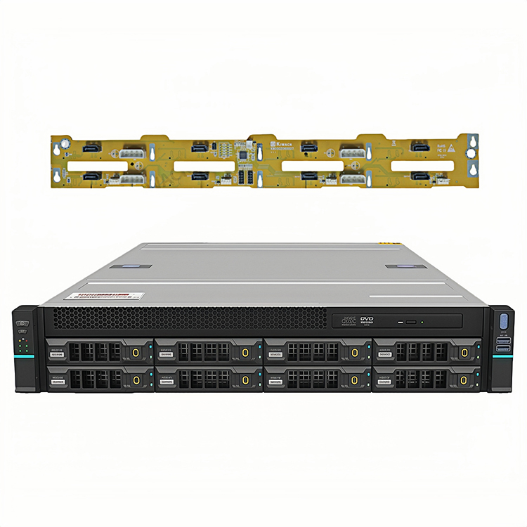
| バックプレーン | PCB blocks most frontal area | Perforation geometry |
| Cable zone | Harnesses form local dams | Production cable routing |
| 扇風機の壁 | Gaps allow local recirculation | Shroud and sealing |
| GPU bank | Dense fins demand pressure | GPU flow direction and impedance |
| CPU/DIMM area | Receives preheated GPU air | Zone order and ducting |
| PSU zone | Competes for chassis air | Independent or shared airflow |
| Rear grille | Exhaust area is too small | Effective open area |
| Rack door/PDU | External restriction rises | Final rack configuration |
Notice what is missing?
“Number of fans.”
Fan quantity comes after the airflow path is understood.
For many rackmount GPU designs, I prefer a fan wall positioned so it creates a controlled pressure boundary between the front intake section and the high-heat compute section.
A common conceptual arrangement is:
Front intake → drives or service area → fan wall → GPU/CPU thermal zones → rear exhaust
But that is not universally correct.
If a storage backplane ahead of the fan wall is highly restrictive, the fans must pull through it. If the fan wall sits upstream from extremely dense passive GPU heatsinks, it must develop enough downstream pressure to force air through those fins.
Geometry wins.
Always.
Do not build a beautiful six-fan wall and then discover that two fans mainly feed empty sheet metal while another two are responsible for four GPUs.
Map fan coverage onto the actual heat sources.
For each fan position, I want to know:
This becomes especially important when GPU dimensions, retainer brackets, PCIe power cables, and support structures occupy the same air channel.
Before freezing the fan wall, verify the accelerator envelope using the measurements in our GPU dimensions and enclosure compatibility guide. GPU length is only one variable; card height, thickness, power-cable bend space, retention structures, and service clearance can all interfere with the intended airflow corridor.
This is one of those details that looks trivial in CAD.
It is not.
Suppose the fan wall produces a pressure difference between its inlet and outlet sides. If there is a large unsealed opening beside the fan tray, air now has an easy recirculation path.
Air takes it.
The fans can pull some air from their own discharge side back toward their intake instead of pulling fresh air through the front restrictions.
You paid for airflow.
You got circulation.
That is why fan trays need deliberate sealing around:
Foam gaskets, formed sheet-metal lips, molded ducts, blanking plates, and properly designed fan carriers can all help.
A 2023 fan-wall cooling study from researchers associated with the University of Hertfordshire provides a useful larger-scale analogy. In its studied configuration, the researchers found an optimum supply-air volume rather than a simple “more airflow is always better” relationship, and their model suggested fan-energy savings of roughly 34% under optimized operation. The experiment concerned a fan-wall data center rather than an individual GPU chassis, so I would not copy its flow numbers into a server design; the broader point is what matters: airflow quantity and fan energy have to be optimized together.
More fan speed is not automatically more thermal intelligence.
A typical chassis fan wall places multiple fans side by side.
Those fans operate broadly as a parallel airflow array. You gain total flow capacity across a larger cross-sectional area, but you should not casually assume static-pressure capability multiplies with fan quantity.
That matters.
Putting eight fans side by side does not make each fan suddenly capable of overcoming eight times the pressure drop.
When very high pressure is required, engineers may consider deeper high-pressure fan designs, dual-rotor configurations, or staged fan arrangements. But each option brings additional power consumption, acoustics, control requirements, cost, and failure behavior.
There is no free air.
Imagine six fans rated at 200 CFM in free air.
The procurement spreadsheet says:
6 × 200 = 1,200 CFM
I would cross that number out.
If the operating point of each fan falls to 120 CFM against the actual chassis restriction, the theoretical combined figure is already closer to 720 CFM, before considering uneven loading, local bypass, installation effects, failed-fan behavior, and control limits.
The right question is:
What does the assembled fan wall deliver at the estimated system pressure?
Ask the fan supplier for the full P-Q curve.
Then test it in the chassis.
A buyer tells me:
“We have eight fans, so it is redundant.”
No.
Eight fans only means eight fans.
Redundancy exists only if the system stays inside its thermal and performance limits after the defined failure occurs.
When a fan stops, three problems can appear immediately.
First, total available airflow falls.
Second, neighboring fans may shift to another operating point.
Third, the stopped fan opening itself can become an unintended air path.
That last one is easy to miss.
If pressure conditions allow reverse flow through the failed fan, part of your healthy fan capacity may circulate through the dead position instead of moving through GPU heatsinks.
Possible design responses include:
But do not call the system N+1 because the drawing shows one extra fan.
Run the test.
If the server needs every fan at 100% PWM during normal operation, it has virtually no airflow control margin left for a failure event.
That is not the kind of redundancy I would sign off on.
High-density GPU server cooling is rarely uniform by accident.
Air follows pressure differences.
If GPU 1 has a low-resistance path while GPU 4 sits behind a cable bundle and denser heatsink geometry, the fan wall can feed them very differently even though they are physically close.
The answer is often zoning.
Depending on architecture, I may divide airflow conceptually into:
Then I ask whether every zone actually needs the same air volume.
Usually not.
You can manipulate distribution using:
This is exactly why our high-density AI computing enclosure case study treats GPU layout, rack power, airflow, structural support, service access, and thermal validation as one engineering problem rather than independent purchasing decisions.
One temperature sensor can lie without technically being wrong.
Put the inlet sensor near the coolest part of the front panel and it may report 23°C.
Meanwhile, recirculated exhaust could be entering another part of the chassis at 31°C.
Which value represents the GPU inlet?
Neither one by itself.
For high-density GPU systems, I want multiple temperature measurements.
At minimum, consider recording:
Then watch the worst device, not the average device.
Averages hide problems.
If seven GPUs run at 67°C and one sits at 88°C, I do not care that the eight-GPU average looks acceptable.
I want to know why GPU 8 is hot.
The GPU power curve is moving faster than many chassis development cycles.
NVIDIA specifies the H100 SXM at up to 700 W and the H200 SXM at up to 700 W. AMD lists its MI300X accelerator at a maximum board power of 750 W. NVIDIA documentation for the HGX B200 gives a configurable maximum of 1,000 W per GPU.
That progression should change how we think about chassis longevity.
A fan wall that barely handles today’s 400 W accelerator configuration may not have enough pressure capability, electrical power, physical space, or control margin for the next hardware revision.
And the industry-level numbers reinforce the same direction. Berkeley Lab’s June 2026 update estimates that U.S. data centers could account for about 11.8% of U.S. electricity consumption by 2030, with modeled scenarios ranging from 9.5% to 15.3%. The report uses equipment shipment data, per-device energy modeling, and cooling simulations rather than simply extrapolating historical electricity use.
That does not tell us how many fans belong in a 4U chassis.
It tells us something more important.
Compute density and cooling demand are not temporary design annoyances.
They are architecture constraints.
There is a point where adding faster fans becomes a bad engineering bargain.
Fan power rises.
Noise rises.
Static pressure may improve.
But available flow gains can flatten as system resistance climbs.
At the same time, the chassis starts losing space to deeper fan modules, larger heatsinks, wider air corridors, ducts, and service clearances.
A 2026 University of Texas at Arlington mechanical-engineering thesis specifically investigated air cooling against direct liquid cooling using a thermal test vehicle modeled after an eight-GPU SXM5-class baseboard, noting the growing challenge created by high accelerator power density and parasitic fan power.
That does not mean every GPU server should use liquid.
I reject that conclusion.
Air cooling remains attractive because it can be mechanically simpler, serviceable, and familiar. But there comes a thermal density where squeezing harder on the fan curve is less sensible than reconsidering the heat-transfer architecture.
Our detailed air cooling versus liquid cooling analysis for high-power systems covers that decision in more depth, including serviceability, pumps, radiators, fan pressure, failure modes, rack density, and liquid-loop requirements.
If I were reviewing a new rackmount GPU server project, this is the sequence I would use.
Do not write:
“8 GPUs.”
Write the exact part number, power range, form factor, heatsink type, airflow orientation, dimensions, retention method, and connector geometry.
Add GPUs, CPUs, memory, storage, networking, motherboard power, conversion losses, and other loads.
Use the workload you actually expect.
Not an idle screenshot.
Decide what air-temperature rise you are designing around.
Then calculate the first-pass airflow requirement.
Draw:
Intake → restriction → fan wall → heat source → restriction → exhaust
If the path is not obvious on paper, it will not magically become obvious inside sheet metal.
Include the production configuration:
Compare required airflow with available static pressure.
Do not approve from free-air CFM.
Every fan should have a job.
Know which components it supports.
Make the intended route easier than the unwanted route.
Decide what the remaining fans do automatically after one fan stops.
Install all intended:
No open covers.
No missing cables.
No “we will test the eighth GPU later.”
Add the production rack door, rear cabling, PDU interference, rail geometry, and realistic inlet conditions.
A server that only passes with the rear door removed has not passed the real deployment.
Bring the system to thermal equilibrium.
Watch for fan saturation, GPU throttling, temperature imbalance, and slow heat soak.
Then remove one fan.
Now the interesting test starts.
If you are asking a server chassis manufacturer to design a fan wall, do not write:
“High-performance cooling required.”
That phrase has almost no engineering value.
Specify:
| RFQ Input | What to Provide |
|---|---|
| GPU configuration | Exact model, count, form factor, power |
| CPU configuration | Exact model and sustained power |
| Total system load | Estimated sustained watts |
| Chassis format | 2U, 4U, 5U, 6U, etc. |
| 気流の方向 | Front-to-rear unless architecture requires otherwise |
| Inlet conditions | Temperature range and altitude |
| Fan redundancy | Normal state and failed-fan requirement |
| GPU limit | Maximum acceptable temperature/throttling behavior |
| ファンコントロール | PWM, tachometer, fault response |
| Filter | Yes/no and expected loading |
| Rack restriction | Door, PDU, cable-management assumptions |
| ノイズ | Maximum target if applicable |
| サービスモデル | Hot-swap fan requirements |
| バリデーション | Workload, test duration, sensor locations |
If this information is not yet defined, our complete custom chassis RFQ guide provides the broader mechanical, material, tolerance, component, quality, and production inputs that should be settled before a supplier quotation becomes meaningful.
I would not approve a GPU Server Chassis because:
I would approve it when the evidence shows:
That is fan wall design.
The rest is fan installation.
A GPU server fan wall is an organized bank of axial or high-pressure fans positioned across the chassis airflow path to generate the airflow and static pressure needed to move cooling air through GPUs, CPUs, memory, storage, backplanes, cables, heatsinks, and exhaust restrictions while maintaining controlled front-to-rear thermal distribution.
Unlike isolated case fans, a fan wall should be designed as a pressure boundary. Its performance depends on fan curves, sealing, chassis resistance, thermal zoning, control logic, and failed-fan behavior.
The number of fans required in a high-density GPU server depends on total sustained heat load, allowable inlet-to-exhaust temperature rise, chassis pressure drop, individual fan performance curves, GPU airflow resistance, redundancy requirements, ambient conditions, and the airflow that must remain available after the defined fan-failure event occurs.
There is therefore no reliable universal answer such as “eight GPUs require eight fans.” Calculate airflow first, estimate resistance second, then select the fan quantity and geometry capable of meeting both requirements.
A GPU server fan wall should be positioned where it can create a controlled pressure difference across the highest-resistance thermal zones while distributing air evenly to accelerators, CPUs, memory, and other components, with placement determined by the front-panel intake, storage layout, backplane restriction, GPU heatsink orientation, exhaust geometry, and service requirements.
Mid-chassis fan walls are common, but the best location depends on system geometry. The correct position is the one that produces useful airflow through the components rather than around them.
An eight-GPU server may require roughly hundreds to well over one thousand CFM depending on total system power and acceptable air-temperature rise; for example, a simplified 7,000 W air-cooled system requires about 821 CFM theoretically at a 15°C rise and about 1,232 CFM at a 10°C rise.
Those values are heat-balance starting points, not fan specifications. Actual fan-wall capacity must account for pressure drop, airflow distribution, altitude, filters, component resistance, fan redundancy, and the real operating point on the fan curve.
Static pressure is the fan wall’s ability to maintain airflow against the resistance created by dense GPU heatsinks, storage backplanes, filters, grilles, cables, ducts, chassis openings, and rack structures, making it more useful than maximum free-air CFM when evaluating fans for a densely populated GPU server chassis.
Two fans with similar maximum airflow can perform very differently inside the same enclosure. Always evaluate the P-Q curve against the estimated or measured system resistance.
Air cooling can support high-density GPU servers when the chassis provides adequate airflow cross-section, static pressure, controlled bypass, acceptable inlet conditions, thermal margin, and fan redundancy, but increasingly high accelerator power can eventually make fan energy, noise, heatsink size, pressure loss, rack density, or component temperatures impractical for an air-only design.
The decision should come from thermal calculations and sustained testing. Do not choose liquid simply because it sounds more advanced, and do not force air cooling after the pressure and temperature data show that it has run out of practical margin.
A fan wall should never be the first cooling component selected.
Start with the GPUs.
Add the CPUs, memory, storage, backplanes, PSU architecture, cable routing, rack restrictions, and expected workload. Calculate the heat. Define the allowable temperature rise. Estimate pressure loss. Then choose fans capable of delivering the required airflow at the actual operating pressure.
And test the failed fan.
If you are developing a 4U, 5U, or 6U high-density GPU Server Chassis, send the exact GPU models, motherboard drawing, power configuration, storage layout, rack depth, target airflow direction, and expected system power to the chassis engineering team before freezing the fan wall.
Explore the available GPU and AI server chassis platforms or request a custom airflow and fan-wall layout based on your production hardware rather than a generic CFM target.

Comments