저희와 상담해 보세요 서버 섀시 엔지니어 및 영업팀




구독자 24,000명
사용 목적, 섀시 유형, 랙 높이, 마더보드, GPU, 드라이브 베이, 전원 공급 장치, 냉각 시스템, I/O 및 주문 수량을 알려주십시오. 당사의 엔지니어 및 영업팀이 귀사의 프로젝트에 적합한 표준 모델 또는 OEM/ODM 구성을 추천해 드리겠습니다.

AI 하드웨어는 “고밀도’의 의미를 바꿔 놓았다.”
몇 년 전만 해도 서버 인클로저 프로젝트는 마더보드 크기, 드라이브 베이, PCIe 슬롯, 전원 공급 장치(PSU) 형식, 랙 높이부터 시작되곤 했습니다. 이러한 요소들은 여전히 중요합니다. 하지만 AI 컴퓨팅 프로젝트에는 또 다른 난관이 따릅니다. 작은 공간에 다수의 고출력 가속기가 밀집되어 있고, 전류 수요가 매우 높으며, 무거운 카드, 빽빽한 케이블 묶음, 공간이 제한된 방열판, 고속 네트워킹, 그리고 냉각 하드웨어가 불과 몇 밀리미터에 불과한 공간을 놓고 경쟁해야 하는 상황입니다.
그러면 업무 내용이 완전히 달라집니다.
이제 문제는 더 이상 단순히, “이 케이스에 GPU 8개를 넣을 수 있을까요?”
더 나은 질문은 다음과 같습니다:
“이 섀시에 전체 시스템을 모두 수용하면서도, 열적·전기적·구조적 문제나 유지보수상의 문제 없이 지속적인 작업 부하에서 시스템을 계속 가동할 수 있을까요?”
그것이 바로 진지한 [... ]의 디자인 철학입니다. 맞춤형 AI 서버 섀시.
현재의 랙 규모 AI 플랫폼들은 왜 인클로저 설계에 더 많은 관심을 기울여야 하는지 보여준다.
NVIDIA의 GB300 NVL72 레퍼런스 아키텍처는 72개의 Blackwell Ultra GPU와 36개의 Grace CPU를 통합하고 있습니다. NVIDIA에 따르면, 이 랙은 수냉식이며 8개의 33kW 전원 셸프를 사용하며, 최대 전체 랙 기준 최대 142 kW.
그건 일반적인 서버실 밀도가 아닙니다.
NVIDIA의 별도 ‘미션 컨트롤(Mission Control)’ 전원 관리 문서에는 설계 랙 전력이 GB200 NVL72의 경우 120 kW, GB300 NVL72의 경우 135 kW, 각 노드의 최대 전력 예산은 각각 약 6.7kW와 7.5kW입니다. 이 수치는 전력 예산의 맥락에서 제시된 것이므로 모든 최대 랙 사양과 상호 교환 가능하다고 간주해서는 안 되지만, 현대적인 AI 컴퓨팅이 매우 작은 물리적 공간을 통해 막대한 전력을 소비할 수 있다는 동일한 공학적 현실을 잘 보여줍니다.
| 기준점 | 게재된 그림 | 인클로저 설계에 있어 이것이 의미하는 바 |
|---|---|---|
| NVIDIA GB300 NVL72 | 72개의 GPU + 36개의 Grace CPU | 매우 고밀도인 컴퓨팅, 네트워킹, 전원 및 냉각수 배선 |
| GB300 NVL72 전체 랙 구성 요건 | 최대 142 kW | 열 및 전력 설계는 사후 고려 사항이 되어서는 안 된다 |
| NVIDIA PRS 예제에서 GB300 설계 랙 전력 | 135 kW | 전력 분배와 여유 용량은 시스템 차원에서 고려해야 합니다. |
| PRS 예시에서 GB300의 최대 노드 전력 | 7.5 kW | 개별 컴퓨팅 트레이는 상당한 열 부하를 감당할 수 있다 |
| IEA, 서버 부문 전력 소비 증가세 가속화 | ~30% (기본 시나리오 기준 연간) | 고밀도 가속 컴퓨팅은 앞으로 더욱 보편화될 것으로 보인다 |
더 넓은 맥락에서 볼 때 추세는 같은 방향을 가리키고 있습니다. 국제에너지기구(IEA)의 ‘에너지와 AI’ 분석 보고서에 따르면, 전 세계 데이터센터의 전력 소비량은 약 2030년까지 945 TWh 기본 시나리오에 따르면, 주로 AI 도입에 힘입어 가속 서버의 전력 사용량은 약 연간 30%, 반면 기존 서버의 경우 약 9% 수준이다.
케이스 설계자와 OEM 구매 담당자에게는 이것이 중요한 문제입니다.
하드웨어의 고성능화가 가속화됨에 따라, 전력 밀도, GPU 부하, 냉각 용량, 케이블 관리 및 서비스 접근성이 최우선적인 기계적 요구 사항이 되는 프로젝트가 늘어나고 있습니다.
맞춤형 인클로저 프로젝트를 실패로 이끄는 가장 빠른 방법 중 하나는 컴퓨팅 아키텍처가 안정화되기도 전에 CAD 작업을 시작하는 것입니다.
그러지 마세요.
섀시 지오메트리가 확정되기 전에, 엔지니어링 팀은 예상되는 워크로드와 시스템 내부에 탑재될 주요 구성 요소를 파악해야 합니다.
최소한 다음 항목에 대한 접근을 제한하십시오:
An AI 서버 인클로저 이 통합 패키지를 중심으로 설계되어야 합니다. 나중에 한 부분을 변경하면 나머지 설계 전반에 연쇄적인 영향을 미칠 수 있습니다.
GPU를 교체할까요?
커넥터의 위치가 바뀔 수 있습니다.
전원 공급 장치(PSU)를 교체해야 할까요?
케이블 묶음의 구성이 바뀝니다.
네트워크 카드를 하나 더 추가할까요?
이제 라이저의 형상이 바뀝니다.
팬 두께를 늘릴까요?
갑자기 GPU 전원 케이블을 구부릴 만한 적절한 곳이 없어졌다.
밀리미터는 금세 쌓입니다.
당연한 말처럼 들리겠지만, 이로 인해 막대한 손실을 초래하는 실수가 발생합니다.
섀시에 GPU가 들어간다고 해서 그 GPU가 섀시 안에서 작동한다는 뜻은 아닙니다.
~을 평가할 때 GPU 서버 섀시, 명목상의 카드 크기를 넘어 실제 설치 가능 범위를 확인해야 합니다.
여기에는 카드 본체, 방열판, 전원 커넥터, 커넥터 굽힘 반경, 인접 카드와의 간격, 마더보드 슬롯 위치, 고정 부품, 라이저 위치, 팬 벽, 케이블 배선, 그리고 기술자가 카드를 제거할 때 따라야 할 방향 등이 포함됩니다.
거대 가속기는 또 다른 문제, 즉 중력을 야기한다.
긴 카드의 경우 PCIe 연결부와 후면 장착 부위에 상당한 하중을 가할 수 있습니다. 운송 중 발생하는 진동은 이러한 문제를 더욱 악화시킵니다. 실험실 작업대에서 정지 상태로 작동할 때는 정상적으로 작동하던 GPU라도, 국제 운송, 랙 설치, 반복적인 유지보수 과정, 또는 고속 팬에서 발생하는 진동을 겪은 후에는 완전히 다른 동작을 보일 수 있습니다.
고밀도 시스템의 경우, GPU 고정 장치는 섀시 구조의 일부로 설계되어야 하며, 출하 이틀 전에야 누군가가 떠올리는 부속품이 되어서는 안 됩니다.
열은 CAD 도면이 얼마나 멋지게 보이는지 따지지 않습니다.
밀집형 서버는 기계적으로는 완벽할 수 있지만, 열 관리 측면에서는 형편없을 수 있다.
공랭식 시스템의 경우, 섀시에는 의도적으로 설계된 공기 흐름 경로가 필요합니다. 공기는 하드웨어가 예상하는 지점으로 유입되어 고저항 부품을 통과한 뒤, 고온 구역을 반복적으로 순환하지 않고 인클로저 밖으로 배출되어야 합니다.
그거 간단해 보이네요.
그렇지 않습니다.
Cables sit in the way. Drive cages sit in the way. PSU housings sit in the way. Tall DIMMs, risers, structural beams, radiator brackets, connectors, filters, backplanes, and even badly positioned sheet-metal flanges can steal pressure from the airflow path.
A High-Density AI Rack therefore cannot be designed by counting fan positions alone.
“Six fans” tells me almost nothing.
I want to know fan dimensions, fan curves, static pressure, restriction, inlet temperature, exhaust path, control strategy, component impedance, and what happens when one fan stops.
Those are useful questions.
| Design Factor | 공기 냉각 | Liquid Cooling |
|---|---|---|
| Mechanical complexity | Lower | 더 높음 |
| Chassis airflow dependency | 매우 높음 | Reduced for liquid-cooled components |
| Facility integration | Usually simpler | May require CDU, manifold, hoses, facility water connection |
| Leak-management requirement | No coolant loop | 예 |
| Service procedures | Familiar to most technicians | Requires coolant-aware service procedures |
| Suitability as heat density rises | Increasingly difficult | Often more practical |
| Internal space competition | Fans and ducts | Cold plates, tubing, manifolds, connectors |
| Failure planning | Fan redundancy and airflow loss | Pump, CDU, leak, flow, and facility-loop scenarios |
Moving to a Liquid-Cooled Server Chassis does not eliminate mechanical-design work. It changes the work.
Now hose paths matter.
Quick disconnect access matters.
Leak detection matters.
Minimum bend radius matters.
The position of manifolds matters.
The technician needs enough room to disconnect and reconnect a loop without removing unrelated hardware or soaking electronics.
NVIDIA’s GB300 NVL72 architecture itself uses rack-level and tray-level leakage detection alongside liquid cooling, which is a useful reminder that coolant management is part of the system architecture, not simply a cold plate bolted onto a GPU.
Power distribution is often treated as an electrical topic.
Inside a dense enclosure, it is also very much a mechanical topic.
High-current power means larger connectors, more cables, tighter bend limitations, additional busbar considerations, higher connector temperatures, and less freedom to route wiring through whatever space remains after the “important” components are installed.
The power architecture needs physical territory.
Reserve it.
A chassis designed around multiple accelerators may need redundant power supplies, high-current distribution, accessible connectors, safe cable separation, airflow around the PSU zone, and room to replace a failed module without pulling the server apart.
여기에서 고밀도 서버 섀시 can go wrong even when the component list looks perfectly compatible on paper.
Everything fits.
Nothing is serviceable.
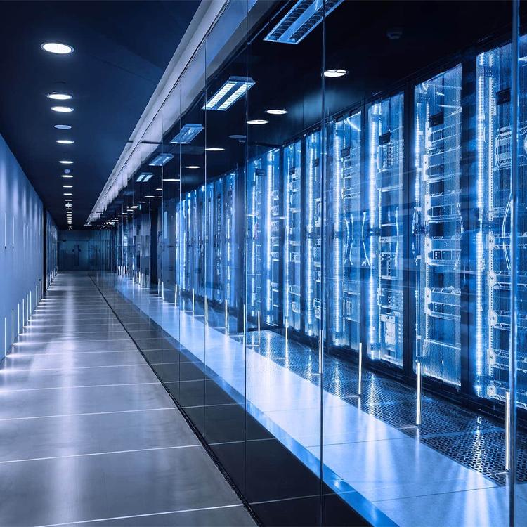
Recently, while reviewing industry discussions, I came across an older r/sysadmin thread about high-density rack cooling that stuck with me.
The original poster had several NVIDIA DGX systems plus storage equipment and was exploring how to fit roughly 30–40 kW into one rack. One participant described operating cabinets at up to about 36 kW and said the margin during cooling failure could be brutally small—around 20 seconds before thermal shutdown for many systems in that specific deployment. Other engineers in the thread repeatedly raised the same concerns: cooling availability, facility power, emergency shutdown, plumbing, maintenance expertise, and the risks created by concentrating so much heat in one cabinet.
That discussion caught my attention because buyers sometimes start a custom AI project with one seductive question:
How much compute can we squeeze into this space?
Wrong first question.
The better one is:
How much compute can this enclosure support continuously, safely, and serviceably under the real facility conditions?
A chassis can look fantastic on a CAD screen. Every component fits. Every rack unit is occupied.
Then the workload starts.
Fans ramp.
Cable temperatures rise.
GPU exhaust collides with another heat source.
One component throttles.
A technician tries to remove a card and discovers that three cables and a manifold are blocking it.
That is not high-density engineering.
That is high-density packaging.
There is a difference.
Maximum component density is often a bad design target for a custom AI enclosure.
Yes, I said it.
“Eight GPUs in 4U” looks great in a comparison table.
“Maximum compute per rack unit” looks great in a procurement presentation.
But one more GPU is worthless if adding it creates poor airflow, thermal throttling, inaccessible connectors, overloaded power routing, difficult field repairs, or zero margin when room conditions drift away from the perfect laboratory assumption.
The winning enclosure is not automatically the smallest one.
For many projects, I would rather build a slightly larger chassis with predictable airflow, solid GPU support, clean power distribution, logical cable routes, accessible fans, and enough room for technicians to work than win a density contest that makes the finished system miserable to operate.
The best high-density enclosure is the one that can sustain the workload.
Not the one that wins the Tetris game.
Ask a simple question during CAD review:
What fails first, and how do we replace it?
Then physically simulate the answer.
Can the technician replace a fan without removing GPUs?
Can the PSU come out from the rear?
Can a network adapter be accessed without disturbing coolant hoses?
Can a GPU be removed vertically or horizontally without disconnecting unrelated cables?
Can the front panel be serviced without pulling the complete server?
Can a leaking fitting be reached quickly?
Can a failed boot drive be swapped without touching the compute section?
These questions are not glamorous.
They save money.
For a system integrator building 50, 100, or 500 machines, a few extra minutes of service time per unit becomes real operational cost. A poor access sequence also raises the chance that technicians damage nearby cables, connectors, cards, or tubing while fixing something unrelated.
That is why a Custom Rackmount Enclosure should be designed not only for assembly but also for disassembly.
Production engineers build it once.
Your customer may service it for years.
AI servers are heavy.
Sometimes extremely heavy.
The chassis has to manage that load during assembly, transport, rack insertion, normal operation, and maintenance. Long GPU cards, multiple PSUs, large motherboards, copper heat sinks, radiators, manifolds, and dense storage can all shift the center of mass.
확인:
A bracket may look insignificant in isolation.
Multiply that tiny deflection across a long heavy card, add shipping vibration, then repeat it across a production batch.
Now it matters.
A prototype is not just a metal sample for checking whether the screw holes line up.
Use it aggressively.
Load the actual motherboard.
Install the actual GPUs.
Use production-equivalent power cables.
Install the same risers, drives, network adapters, fans, radiators, tubing, PSUs, rails, and front-panel assemblies expected in the finished server.
Then test the ugly conditions.
Check component installation, card retention, cable routing, connector access, chassis stiffness, rail engagement, lid fit, and service sequence.
Run representative workloads. Measure inlet and exhaust temperatures, component temperatures, fan behavior, hot zones, and performance under expected ambient conditions.
Confirm PSU loading, redundancy behavior, cable temperatures, connector temperatures, power distribution, and startup behavior.
What happens when one fan stops?
What happens when a coolant pump or facility loop has a problem?
What happens when one PSU fails?
What happens if a filter becomes partially obstructed?
What happens when ambient temperature increases?
A machine that passes a thermal test but arrives with GPUs shifted inside the chassis is still a failed design.
Test packaging, retention, vibration resistance, brackets, fasteners, and heavy-component support before volume shipment.
A weak RFQ produces assumptions.
Assumptions produce revisions.
Revisions cost time.
For a custom AI chassis project, send the supplier enough information to evaluate the complete system architecture rather than quote an empty metal shell.
A useful RFQ package should include:
| RFQ Input | Information to Provide |
|---|---|
| 폼 팩터 | Target U height, width, depth |
| 마더보드 | Model, dimensions, drawings, mounting locations |
| GPU | Exact model, quantity, dimensions, slot width, power |
| CPU | Platform, quantity, cooler |
| 메모리 | DIMM configuration and clearance requirements |
| 스토리지 | Drive type, quantity, hot-swap requirement |
| 네트워킹 | NIC/DPU model and quantity |
| PCIe | Slot map, risers, switches, bifurcation requirements |
| 전원 | PSU type, redundancy, total target power |
| 냉각 | Air/liquid, fan specification, radiator/manifold requirements |
| I/O | Front and rear port requirements |
| Structure | GPU retention, handles, rails, reinforcement |
| 서비스 | Components requiring tool-less or rapid access |
| 브랜딩 | Logo, color, silk screen, labels |
| Production | Prototype quantity, annual volume, target schedule |
| Market | Destination countries and compliance requirements |
The more complete the input, the earlier mechanical conflicts can be found.
Finding a 12 mm interference in CAD is cheap.
Finding it after tooling, fabrication, assembly, and international shipping is not.
High-density AI systems force mechanical, thermal, electrical, and facility engineering to meet in one box.
That is why a 맞춤형 AI 서버 섀시 should never be specified by rack height and GPU count alone.
Start with the complete bill of materials.
Model the heat.
Reserve space for power.
Support the GPUs.
Plan the cable paths.
Decide the cooling architecture early.
Design access around the parts most likely to need service.
Then prototype the actual system—not an empty enclosure.
AI compute density will keep rising. The IEA’s projections for accelerated-server electricity use and today’s 100 kW-plus rack architectures already point in that direction.
The manufacturers and system integrators that handle that density well will not be the ones who simply make smaller boxes.
They will be the ones who understand what has to happen inside those boxes when the workload hits 100%.
Short answer: A custom AI server chassis is an enclosure engineered around a specific combination of GPUs, CPUs, motherboard, storage, networking, power, cooling, and rack requirements.
Unlike a generic server case, its internal layout can be optimized for accelerator spacing, structural support, airflow, liquid cooling, cable routing, redundant power, and maintenance access.
Short answer: A high-density server chassis places a large amount of compute, storage, or accelerator hardware into a limited rack space while maintaining adequate power delivery, cooling, structural support, and service access.
Density should be evaluated by usable sustained performance, not component count alone.
Short answer: No. A smaller chassis can improve rack density, but 5U or 6U may provide better cooling capacity, GPU spacing, cable routing, expansion, and maintenance access.
The correct form factor depends on GPU type, power, cooling strategy, motherboard layout, and operational requirements.
Short answer: Liquid cooling becomes attractive when heat density, accelerator power, rack density, noise limits, or airflow restrictions make conventional air cooling difficult to manage efficiently.
The decision must also consider facility water, CDU requirements, manifolds, leak management, service procedures, and redundancy.
Short answer: Provide the GPU, motherboard, CPU, PSU, storage, networking, PCIe, cooling, rack dimensions, I/O, rail requirements, production volume, and target market.
Exact component drawings are far more useful than generic statements such as “8-GPU AI server.”
Short answer: Heavy GPUs can place mechanical stress on PCIe slots, brackets, and chassis structures during operation, shipping, and maintenance.
Proper retention controls card movement, distributes mechanical load, and reduces the risk of connector or board damage.
Short answer: Usually not. The better target is the highest practical compute density that can maintain thermal performance, reliable power delivery, structural stability, and acceptable service access.
One extra GPU is not valuable if the resulting system throttles or becomes difficult to maintain.
Comments