저희와 상담해 보세요 서버 섀시 엔지니어 및 영업팀




구독자 24,000명
사용 목적, 섀시 유형, 랙 높이, 마더보드, GPU, 드라이브 베이, 전원 공급 장치, 냉각 시스템, I/O 및 주문 수량을 알려주십시오. 당사의 엔지니어 및 영업팀이 귀사의 프로젝트에 적합한 표준 모델 또는 OEM/ODM 구성을 추천해 드리겠습니다.

A custom chassis project rarely fails because somebody forgot how to draw sheet metal.
It fails earlier.
A motherboard changes. A GPU turns out to be 18 mm taller than the preliminary specification. The PSU connector needs more cable bend space than expected. A drive cage blocks the fan wall. A purchasing team asks for a lower unit price after the design has already been built around expensive machining. Or a drawing carries ±0.1 mm tolerances across dimensions that never needed them.
By then, the CAD may look finished.
The project isn’t.
For engineers, system integrators, OEM product teams, and sourcing managers, good Custom Chassis Design starts with inputs. Geometry comes later. The supplier’s job is to translate system requirements into an enclosure that can actually be fabricated, assembled, cooled, serviced, shipped, and repeated in production.
That is why the best starting point is a structured set of Chassis Design Requirements covering the complete hardware architecture rather than a vague request such as, “We need a custom 4U case.”
Here is an unpopular view in custom chassis manufacturing:
A finished 3D model can be less useful than a rough sketch with ten well-defined engineering inputs.
That sounds backwards.
그렇지 않습니다.
If a STEP file tells us where a hole is but not what must pass through it, how accurately the mating part must align, whether the connector will change, or whether a technician needs finger access behind it, the model contains geometry without intent.
And intent controls manufacturing decisions.
This matters financially as well. Autodesk’s 2025 State of Design & Make research found that 33% of leaders identified cost control as their main business challenge. The study covered 5,594 industry leaders, futurists, and experts across Design and Make sectors. You can review the Autodesk business-challenges findings 그리고 study methodology
Cost pressure is not something to discuss after the drawings are released.
It belongs in the design brief.
Protolabs makes the same business case from a manufacturing angle. Its Innovation in Manufacturing 2026 report states that research indicates early design-to-cost and DFM practices can reduce product-development time and material costs by 15% to 30%.
That is a big number.
And it starts before production.
| Design Input | What the Supplier Needs | What Can Go Wrong If It Is Missing |
|---|---|---|
| 애플리케이션 | Workload, installation environment, duty cycle | Wrong enclosure architecture |
| 폼 팩터 | Rack height, width, depth, wallmount/desktop/rack use | Installation conflict |
| 마더보드 | Exact drawing, hole pattern, rear I/O | Standoff and I/O misalignment |
| GPU/PCIe | Card length, height, width, power connectors | Card interference or blocked airflow |
| 스토리지 | Drive count, size, hot-swap needs, backplane | Unserviceable bays or cable congestion |
| PSU | Format, wattage, redundancy, connector location | Cable or airflow conflict |
| 냉각 | Heat load, fans, airflow direction, filters | Thermal throttling or fan noise |
| Interfaces | USB, LAN, buttons, LEDs, custom connectors | Panel redesign |
| 재료 | Steel/aluminum grade and thickness | Excess weight, flex, cost, or corrosion |
| 허용 오차 | Functional dimensions and datum strategy | Fit problems or unnecessary cost |
| Finish | Powder coat, plating, anodizing, printing | Grounding or cosmetic issues |
| 서비스 가능성 | Access sequence, removable modules | Slow field maintenance |
| Compliance | Destination market and system configuration | Late documentation or testing problems |
| Volume | Prototype quantity and annual demand | Wrong manufacturing process |
| Target cost | Target unit cost or acceptable range | Design exceeds commercial limits |
The rest of this guide explains why each one changes the chassis.
Before discussing thickness, bends, vents, or surface finish, answer a simpler question:
What does this chassis have to do?
A rackmount AI server behaves differently from a short-depth network appliance. An industrial computer mounted beside a production machine has different requirements from a NAS enclosure installed in a controlled server room.
Define:
A Custom Electronic Chassis designed for industrial computing, for example, may need front-access filters, stronger card retention, controlled cable routing, specific mounting orientation, and easier field maintenance.
Those are not cosmetic choices.
They determine the architecture.
“How big should the chassis be?”
That is usually the wrong first question.
Ask instead:
What space are we allowed to occupy?
For a rackmount project, define:
Height is especially deceptive.
Moving from 2U to 4U does not merely double the available vertical space. It changes the cooling options, GPU orientation, fan diameter, storage density, expansion possibilities, PSU layout, cable routing, and service approach.
If that choice has not been made yet, compare the site’s guide to 1U, 2U, and 4U chassis form factors before freezing the mechanical envelope.
Never design around “ATX motherboard” alone if you can provide the actual motherboard.
Form-factor labels are useful.
Part numbers are better.
For the motherboard, provide:
Why so much detail?
Because “it fits ATX” does not mean the complete system fits.
A CPU heatsink can collide with a lid stiffener. An EPS connector can sit directly behind a fan wall. A tall DIMM can interfere with an internal bracket. A cable socket can become almost impossible to disconnect once the assembly is inside the enclosure.
The board outline is only the beginning.
A specification saying “supports four GPUs” tells us surprisingly little.
We need the cards.
At minimum, specify:
Then add clearance.
A connector sticking out of the end of a 300 mm GPU means the system may need considerably more than 300 mm of internal depth.
The same applies to NICs, accelerator cards, RAID cards, capture cards, FPGA boards, and proprietary PCIe assemblies.
Do not measure only metal against metal.
Measure the assembled system.
“Eight drives.”
Okay. Which eight?
There is a huge mechanical difference between eight internal 2.5-inch SSDs and eight front-accessible 3.5-inch hot-swap drives.
Define:
Hot-swap storage drives chassis depth, front-panel geometry, PCB placement, airflow resistance, and service access.
The backplane deserves particular attention.
It is not an accessory you casually squeeze in later.
The PSU occupies volume.
Its wires occupy more.
For power, specify:
Now imagine changing from a standard ATX PSU to redundant CRPS units after the chassis layout is nearly complete.
Rear-panel geometry changes.
Mounting changes.
Cooling changes.
Cabling changes.
Possibly the chassis depth changes too.
This is why the power architecture belongs in the first design meeting.
A fan count is not a thermal specification.
“Four 80 mm fans” tells the chassis engineer what hardware somebody wants to install. It does not tell us whether the system will cool.
Instead, define:
Then look at resistance.
Drive cages resist airflow.
Dense heatsinks resist airflow.
Filters resist airflow.
Cables resist airflow.
Small perforations resist airflow.
A fan’s free-air CFM figure therefore does not equal airflow through the assembled chassis.
For high-power GPU platforms, the site’s GPU and AI server chassis examples show why card density, cooling architecture, power integration, and enclosure size have to be treated as one system rather than four independent specifications.
No airflow path?
No design.
Cables have thickness.
They also bend badly when engineers pretend they do not.
A good chassis input package should include:
This becomes particularly important around GPUs, backplanes, PSUs, front I/O boards, and dense 1U or 2U platforms.
A component may physically fit while its cable cannot.
That still counts as “doesn’t fit.”
Provide the exact interfaces:
For every connector, define its location and tolerance relative to the PCB or bracket behind it.
This is where a good Sheet Metal Chassis Design differs from a generic enclosure sketch.
The panel and the electronics must agree.
Steel or aluminum?
There is no universal winner.
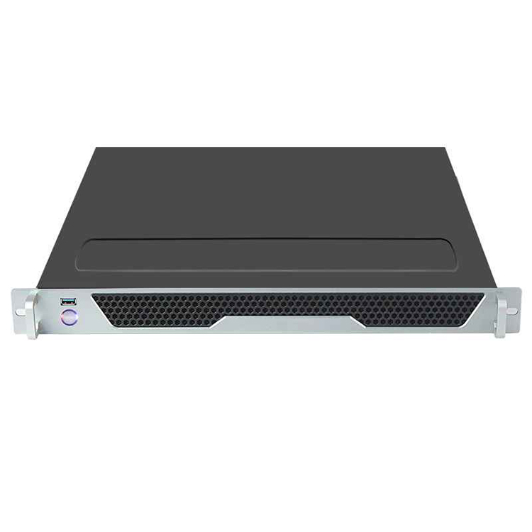
Steel generally provides good stiffness and is widely used for cost-sensitive rackmount structures. Aluminum can reduce weight and may offer advantages for certain thermal, corrosion, or appearance requirements.
But material grade and thickness matter just as much as the material family.
For Sheet Metal Enclosure Design, buyers should define the intended metal, thickness range, structural loading, corrosion environment, grounding needs, and finish rather than simply writing “metal chassis” on an RFQ. You can see examples of steel material and thickness combinations in the site’s wallmount industrial chassis 범위입니다.
Material also affects:
One millimeter matters.
Sometimes a lot.
Engineers love tight tolerances.
Factories invoice for them.
Those two facts deserve to meet earlier.
Protolabs’ published sheet-metal fabrication design guidelines show how tolerance capability changes according to the feature relationship. For material under 0.13 inch thick, it publishes 0.005 inch (0.13 mm) for edge-to-edge, edge-to-hole, and hole-to-hole features on one surface, while measurements across three or more bends are listed at 0.030 inch (0.76 mm).
That difference matters.
A dimension across several bends should not automatically receive the same tolerance as two laser-cut holes on a flat panel.
Use tight tolerances where function requires them:
Leave nonfunctional dimensions reasonable.
The goal is not to make the drawing look precise.
The goal is to make the product repeatable.
Here is a common prototype surprise:
Everything fits individually.
Nothing can be assembled.
Why?
Because assembly sequence was ignored.
Ask:
These questions influence panel split lines, bracket design, fastener location, captive hardware, connector orientation, and access openings.
여기에서 Chassis Design for Manufacturability becomes more than reducing laser cuts or bends. A manufacturable chassis should also be straightforward to assemble repeatedly without operators wrestling with hidden screws, trapped cables, or impossible tool angles.
Recently, while browsing a CNC engineering discussion, I came across a chassis project that captured this problem perfectly.
The designer wanted to machine essentially an entire small-form-factor PC chassis from one large piece of aluminum.
Beautiful idea.
The budget was around $1,000.
Experienced machinists immediately started pointing out the amount of material removal, machining time, fixturing, and overall cost involved. The designer eventually abandoned the monolithic concept and moved back toward a chassis made from six simpler, flatter pieces.
That story stuck with me because the mistake happens in different forms in B2B projects all the time.
People design geometry first.
Then they ask what it costs.
Reverse that sequence.
If your commercial target is $80 per chassis at 2,000 units annually, tell the engineering team. If the target is a $1,500 low-volume scientific enclosure where rigidity matters more than unit price, tell them that too.
Different economics produce different designs.
Prototype quantity and annual demand belong in the RFQ.
A five-piece engineering run, a 100-piece pilot, and a 10,000-piece annual program should not automatically use identical tooling and processes.
Volume affects decisions around:
The economic scale behind outsourced fabrication is significant. Grand View Research valued the global contract fabrication services market at $444.9 billion in 2025 and estimates it will grow from $477.0 billion in 2026 to $795.2 billion by 2033, a 7.6% CAGR. It also reported Asia-Pacific at 56% of 2025 market revenue.
That market includes cutting, forming, welding, machining, finishing, and assembly—the exact process chain behind many chassis programs.
For buyers considering Custom Chassis Manufacturing, the question is therefore not simply, “Can this factory make my drawing?”
Ask:
Can this design scale using the right process?
A finish is not only about color.
Consider:
Then define what must remain conductive.
If grounding depends on metal-to-metal contact, indiscriminately coating every mating surface can create another problem.
Masking locations may be necessary around:
Cosmetic expectations also need limits.
State which surfaces are Class-A visible surfaces and which are hidden inside the chassis.
Otherwise, a buyer may expect consumer-electronics cosmetic standards on internal panels where those standards add cost without adding value.
Do not treat chassis compliance as a checkbox copied from another project.
Define:
A metal box cannot automatically certify the electronics installed inside it.
Power supplies change.
Motherboards change.
Wireless modules appear.
Firmware changes.
Compliance scope may change with them.
Put the destination market in the first RFQ, not in an email two weeks before shipment.
A prototype that looks good can still be a bad production sample.
Check more than finish.
Only then should the prototype become the production reference.
One file called final_chassis_v8_revised_REAL_FINAL.step is not revision control.
Use:
This matters once production begins.
Suppose engineering changes a GPU bracket but purchasing still sends the old drawing to the supplier.
Which version wins?
Without revision control, nobody knows.
A good production package makes that answer boring.
Boring is good.
A useful RFQ package does not need to be pretty.
It needs to be complete.
At minimum, send:
If some details are unknown, say so.
That is better than guessing.
A capable engineering supplier can work through open items during feasibility review. The problem begins when assumptions are hidden inside a drawing and nobody realizes they are assumptions.
Not every requirement needs to be frozen at the same time.
Use three levels.
These define the architecture:
These refine the mechanical solution:
These control repeat manufacturing:
This approach keeps engineering moving without pretending every decision has already been made.
Most buyers ask:
“Can you manufacture this chassis?”
Ask this instead:
“What would you change before manufacturing this chassis at our target volume and cost?”
That question reveals much more.
A supplier who only prices the STEP file may be useful for build-to-print work.
A supplier supporting development should be able to challenge:
That is the real value of early engineering involvement.
The CAD file is not the product.
The repeatable manufactured assembly is.
The most expensive chassis mistakes often begin as missing inputs.
Not bad machining.
Not bad sheet metal.
Missing information.
Good Custom Chassis Design starts by defining what the system contains, where it operates, how much heat it produces, how technicians will service it, what dimensions actually control function, how many units will be built, and what the commercial target is.
Once those inputs are clear, Sheet Metal Chassis Design becomes much more predictable.
So before sending a supplier your STEP file, ask one question:
Have we defined the requirements that created this geometry?
If the answer is no, the project is not ready for production yet.
You need the system dimensions, motherboard, expansion cards, storage, PSU, cooling, I/O, material, finish, tolerances, volume, and installation requirements.
Exact component drawings and model numbers are preferable because generic form-factor labels may not capture connector positions, cooler height, cable clearance, or other interference risks.
No. Early supplier input can identify manufacturing, tolerance, assembly, thermal, and cost problems before they become embedded in the CAD.
A concept model, component list, rough layout, or even dimensioned sketches can be enough to begin a technical feasibility discussion.
The complete system architecture is more important than any single sheet-metal parameter.
Motherboard, cards, storage, PSU, cooling, I/O, installation space, and service requirements interact. Changing one may force changes elsewhere in the enclosure.
Use tight tolerances only where they control functional fit, alignment, or interfaces.
Connector openings, PCB mounts, rails, and mating parts may need tighter control. Large dimensions measured across several bends usually require more allowance than flat laser-cut features.
Yes. Target cost helps the engineering team select realistic materials, processes, part counts, tooling, finishes, and assembly methods.
Without commercial boundaries, engineers may optimize a design technically while creating a product that cannot meet the buyer’s business case.
Volume changes which manufacturing processes make economic sense.
Low-volume prototypes may favor flexible fabrication methods, while repeat production can justify dedicated fixtures, optimized tooling, punching, stamping, or other process changes that lower recurring cost.
Provide heat loads, ambient conditions, fan constraints, airflow direction, filtration requirements, and temperature targets—not fan count alone.
The final airflow depends on resistance from heatsinks, drives, filters, perforations, cables, backplanes, and other internal structures.
A prototype verifies real component fit, assembly sequence, access, airflow, serviceability, finish, and manufacturing behavior.
It can expose problems that are difficult to detect in CAD, especially cable routing, tolerance accumulation, tool access, panel stiffness, and maintenance clearance.

Comments